
Coated slide

a microscope slide and coating technology, applied in the field of coating microscope slides, to achieve the effect of uniform shape dots and biomaterial density, high bonding density, and high wetting performan

Inactive Publication Date: 2011-08-18
HUSHER FREDERICK KNUTE +1
View PDF5 Cites 1 Cited by
  • Summary
  • Abstract
  • Description
  • Claims
  • Application Information

AI Technical Summary

Benefits of technology

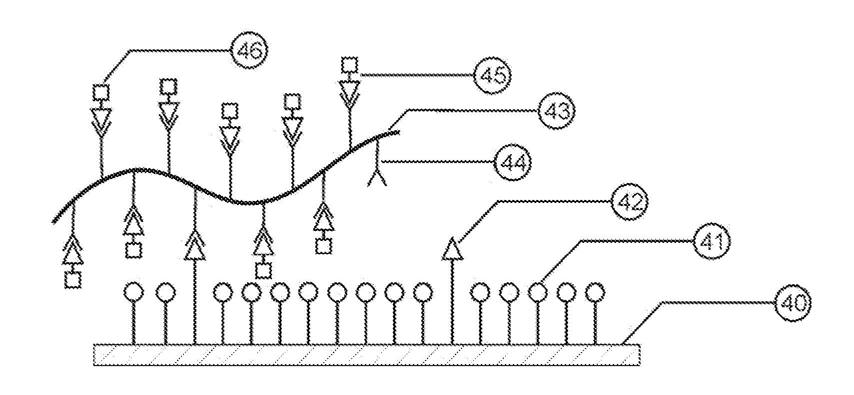
[0013]For the most part, the reactive silanes used to attach biological materials (protein / peptides, cells, and tissue) to slides react with a biomaterial's amine or carboxyl sites. While there are typically a great many amine sites on the biological materials, the density is much lower than the spacing between the silane molecules on the glass surface. However, if covalent bonds are formed, 100% binding density is not required to ensure the biomaterial is sufficiently anchored to the glass. Therefore, the opportunity exists wherein spacer silanes can be used to separate the reactive binding silanes and influence the overall hydrophilic / hydrophobic behavior of the surface. The spacer silanes are chosen such that they have a shorter terminal end spacer arm than the reactive silanes. The resulting mixture forms a 3-D structure on the slides, which contains isolated covalent binding sites surrounded by hydrophobic / hydrophilic spacers. The 3-D reactive structure depth can be enhanced by grafting a reactive polymer chain to the covalent binding silane sites. This increased depth provides a conformal binding mechanism that draws in tissue samples as it dries with continued binding attachment. More importantly for protein deposits, the polymer strand will tend to wrap itself around the protein, which greatly retards the protein's ability to uncoil if denaturing stimulus is applied. There is a limitation on the length of the polymer chain; if too long, the polymer chain will fall over and hinder the wettability provided by the hydrophilic spacers. Thus, the polymer strand length should be shorter than the spacing between the reactive silane binding sites.
[0019]Generally, all biomaterial reactive moieties are hydrophobic, which can lead to the formation of micro-bubbles and initial skittish behavior of the tissue section on the slide. Micro-bubbles form on a hydrophobic surface because upon entrance of the slide into the bath, the liquid cannot fully displace the air trapped in the porous structure. Micro-bubbles remaining between the coating and the tissue section will usually form voids. These voids will rupture the tissue during the HIER process and can cause loss of tissue if not eliminated. It is desirable then to apply a temporary non-reactive hydrophilic topcoat to the slide. This surface treatment ensures that the slide will not support micro-bubble adhesion when initially placed into the sectioned tissue bath as well as promote fast draining of the water, which allows the tissue to settle down onto the slide surface before it can dry and be left with a lifted portion. An additional benefit of the surface treatment is that the reactive silane moieties are generally encapsulated and thus protected from unintended reactions with airborne contamination prior to the application of a tissue section. Such a material could be a short length hydrophilic polymer. The polymer is released into the sectioned tissue bath upon immersion, where it remains effectively inert to any tissue sections because of the very low concentration density. The application of such a hydrophilic material onto a hydrophobic surface would normally cause the hydrophilic material to be disassociated and rejected from the slide unless applied correctly.
[0020]For protein / peptide / enzyme deposits a different set of conditions arise. When these biomaterials are deposited, they are carried in a printing buffer slurry. The attributes of the buffer and the structure of the slide coating must work together to enable monotonic single layer deposits. Because the biomaterials are so small, the movement of the slurry is affected by the height modulation, porosity, Zeta potential of the biomaterials, and the viscosity, and pH of the buffer. If a single-silane coating is used, the biomaterials tend to be repelled by the coating to give the appearance that the coating is strongly hydrophobic. If another long spacer arm hydrophobic silane is added at a low concentration, it acts to stop the movement of the slurry from excessive spreading before capture can take place. This behavior is realized because there is sufficient obstruction of the slurry movement that the buffer is able to drop into the porosity and leave the biomaterial stranded above. Balance must be reached between the coating and the slurry such that this can occur. Very large deposits, one centimeter (1 cm) in diameter, are possible as a uniform and round single layer with very crisp edge detail.
[0048]These materials enable the user to push the surface wettability lower, more hydrophobic, while keeping the reactive silanes spaced sufficiently.
[0064]Assuming for the moment that the density of epoxide sites is higher than whatever amine structure exists on a biomaterial, to obtain the highest efficiency in bonding density, the pH of the solution that contains the biomaterials would need to be at least 9.0. For tissue mounting, this presents no particular constraints, but for protein / peptide deposits this greatly affects the wetting ability of the slurry and thus results in non-uniform shape dots and uneven biomaterial density. However, if a wetting agent is added to the protein slurry, then the pH can be decreased to 6-7 and the wetting performance will remain high, resulting in uniform shape dots and biomaterial density.

Problems solved by technology

While these singular coatings can produce high adhesion densities, the reactive end points are generally hydrophobic, which will impact the movement of fluids during the initial biomaterial deposit and in the staining activities.
Secondly, the reactive spacers provide additional binding sites.

Method used


Image

  • Coated slide
  • Coated slide
  • Coated slide

Examples


second embodiment

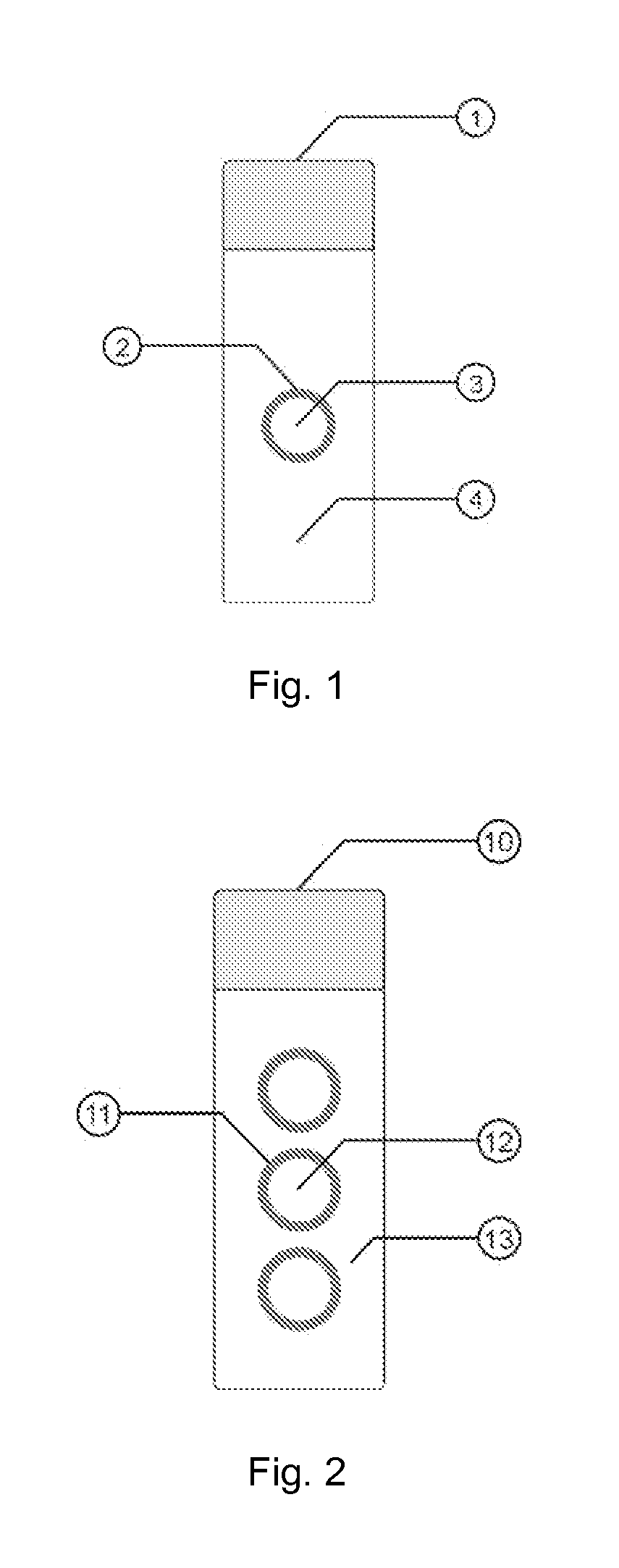
[0076]FIG. 2 shows a microscope slide 10. The microscope slide 10 has a coating 12 and 13 of a silane mixture bonded to the microscope slide 1. Three hydrophobic barrier rings 11 are formed on a top surface of the microscope slide 10.

third embodiment

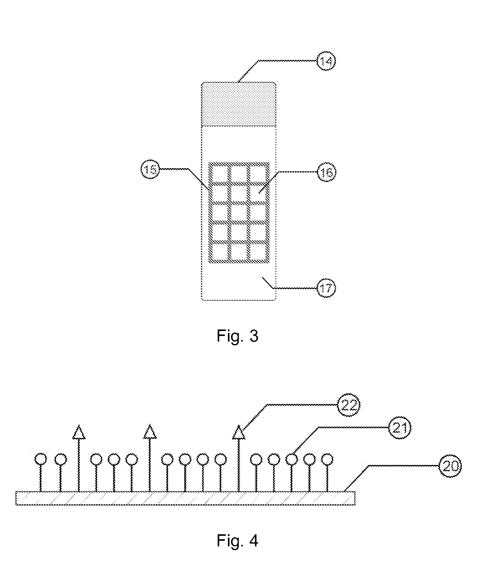
[0077]FIG. 3 shows a microscope slide 14. The microscope slide 14 has a grid 15 of hydrophobic barriers to define an array of sample cells on a top face of the microscope slide 14. The microscope slide 14 has a coating 16 on cells within the grid 15. A silane coating 17 is applied outside of the grid 15.

[0078]FIG. 4 shows a coated slide. A microscope slide 20 is provided. Spacer silanes 21 have interposed reactive silanes 22. The spacer silanes 21 can be reactive silanes or non-reactive silanes. The spacer silanes 21 have a short arm length relative to the arm length of the reactive silanes 22. The reactive silanes 22 are spaced apart from each other a greater distance than the height of the reactive silanes 22.

[0079]FIG. 5 shows a coated slide with a polymer coating. A microscope slide 30 is the substrate. Spacer silanes 31 are bonded to the microscope slide 30. The spacer silanes 31 can be reactive silanes or non-reactive silanes. Reactive silanes 32 which are taller than the spac...


PUM

PropertyMeasurementUnit
Lengthaaaaaaaaaa
Adhesion strengthaaaaaaaaaa
Hydrophilicityaaaaaaaaaa

Abstract

A single layer multi-silane coating construct displays controlled covalent attachment between biological materials and microscope slide substrates. Choice of various silanation reagents and their mix ratios provides control over the overall hydrophilic / hydrophobic surface behavior, attachment site density, and reactive moiety type. Both two-dimensional (2d) and three-dimensional (3d) configurations use the same foundation basics. Improved biological adhesion and fluid flow during subsequent processing is achieved. The 3d configuration offers conformal adhesion for those tissue materials that are not monotonically flat as well as multiple point capture of protein / peptides.

Description

TECHNICAL FIELD[0001]The field of the invention is coated microscope slides.BACKGROUND ART[0002]Gedig et al. (Pub. No. US 2005 / 0042455) is titled, “Coating for Various Types of Substrate and Method for the Production Thereof.” The substrate structure consists of a base glass, a silane coupler, and an adhesion promoting layer that lays entirely parallel to the silane substrate coupler. No structure that goes directly from the silane end to some point on a PAAH backbone is taught. An adhesion-mediating material is described. The adhesion-mediating material is described as a polyamine.[0003]McGall et al. (Pub. No. US 2007 / 0275411) is titled, “Silane Mixtures.” This publication involves the use of mixed silanes for producing a controlled density of reactive sites that are initially capped and then uncapped to attach polymers thereto. No mention is made regarding controlling the hydrophilic / hydrophobic nature of the slide coating. The publication does not involve the attachment of polyme...

Claims


Application Information

Patent Timeline
IPC IPC(8): C09J7/02B32B27/06B32B17/06B32B7/04B32B3/30
CPCC03C17/30C03C17/3405C03C2217/75Y10T428/2852G01N33/54353Y10T428/24612C03C2218/355Y10T428/31612Y10T428/31663
Inventor HUSHER, FREDERICK KNUTESHUM, JEE JONG
Owner HUSHER FREDERICK KNUTE
Learn More