
Pneumatic Tire

Active Publication Date: 2019-11-14
YOKOHAMA RUBBER CO LTD
View PDF0 Cites 3 Cited by
  • Summary
  • Abstract
  • Description
  • Claims
  • Application Information

AI Technical Summary

Benefits of technology

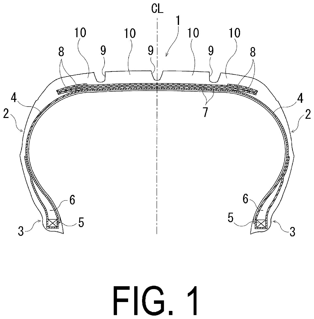
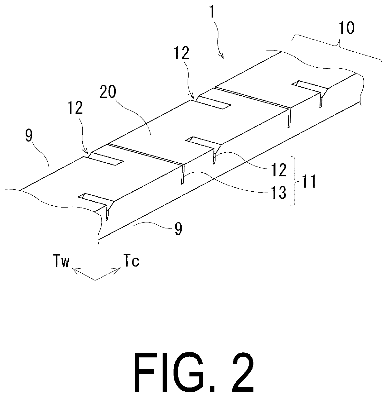
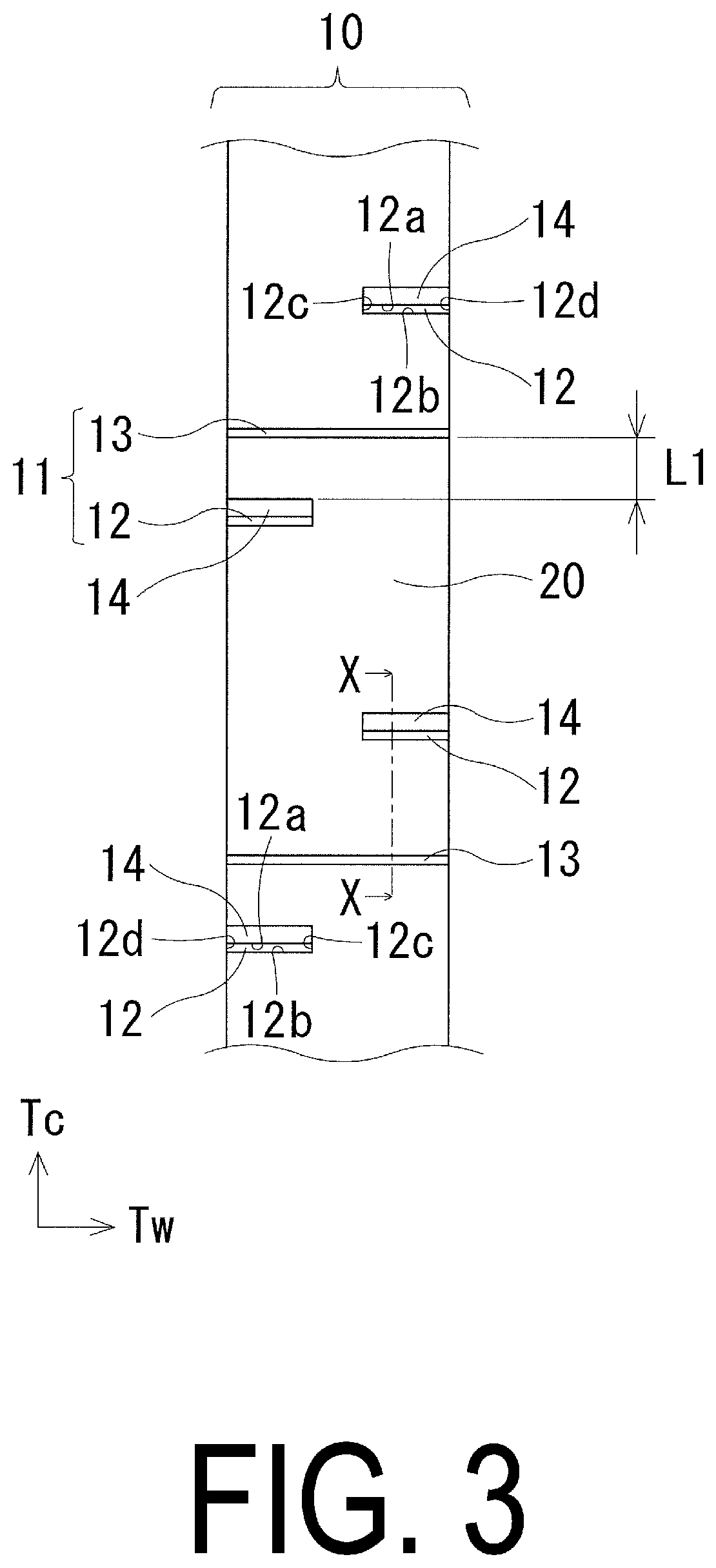
The present technology describes a tire with improved wet performance by designing shapes of sipes in its tread portion. The chamfered sipe with a chamfer portion and the non-chamfered sipe without chamfer provide improved drainage performance at contact with the ground. The non-chamfered sipe helps to supply drainage and also bears deformation of the tread portion at contact with the ground, which contributes to the suppression of crush of the chamfer portion of the chamfered sipe and further improves wet performance. The chamfered sipe also has an opening with a width and chamfer portion with a rectangular cross-sectional shape to secure sufficient groove volume against deformation of the tread portion and improve drainage performance. The relationship between the curvature radius of the arc forming the tread profile and the curvature radius of the outer contour line of the at least one rib including the chamfered sipe also contributes to the improvement of wet performance.

Problems solved by technology

Unfortunately, in a configuration in which a chamfer portion is simply added to a sipe, the chamfer portion is crushed due to deformation of a tread portion at contact with the ground, so the chamfer portion may not effectively serve as a discharge channel.
Thus, drainage performance may not be sufficiently secured.

Method used


Image

  • Pneumatic Tire
  • Pneumatic Tire
  • Pneumatic Tire

Examples


examples

[0056]Using a pneumatic tire of the size 195 / 65R15 including, in a tread portion, a plurality of main grooves extending in the tire circumferential direction, and a plurality of ribs defined by a pair of the plurality of main grooves adjacent to each other, tires of Conventional Example, Comparative Examples 1, 2, and Examples 1 to 10 were produced according to Tables 1 and 2 showing: whether a chamfered sipe is provided; whether a non-chamfered sipe is provided; a distance L1 (mm) between a chamfered sipe and a non-chamfered sipe; a ratio (Nd / Cd) of a depth of a non-chamfered sipe to a depth of a chamfered sipe; a difference (θC-θN) between inclination angles of a chamfered sipe and a non-chamfered sipe; placement of a non-chamfered sipe (one side or both sides); a width of a non-chamfered sipe (uniform or gradual increase); a width Cw (mm) of an opening of a chamfered sipe in a ground contact surface; a cross-sectional shape of a chamfer portion; whether a non-chamfered sipe commu...


PUM


Abstract

A pneumatic tire includes, in a tread portion, main grooves extending in a circumferential direction; ribs defined by the main grooves; at least one rib comprising sipes extending in a lateral direction; the sipes comprising a chamfered sipe with a chamfer portion provided on at least one edge, and a non-chamfered sipe with no chamfer portion provided on an edge; the chamfered sipe comprising one end portion terminating in the at least one rib and another end portion communicating with one of the main grooves located on either side of the at least one rib; a plurality of the chamfered sipes communicating with one of the main grooves located on either side of the at least one rib being alternately disposed in the circumferential direction; and the non-chamfered sipe being disposed close to the chamfered sipe on at least one side in the circumferential direction.

Description

TECHNICAL FIELD[0001]The present technology relates to a pneumatic tire and particularly relates to a pneumatic tire with improved wet performance by devising shapes of sipes provided in its tread portion.BACKGROUND ART[0002]In general, a pneumatic tire includes a tread portion provided with a plurality of grooves and sipes to obtain wet performance. To improve braking performance which is an index of tire performance on a wet road surface, the grooves and the sipes are required to be improved in drainage performance.[0003]As a method of improving drainage performance, providing a chamfer portion in an edge of a sipe provided in a tread portion has been proposed (e.g., Japan Unexamined Patent Publication No. 2016-88469). In this case, the chamfer portion serves as a discharge channel to improve drainage performance of a ground contact surface, so that improvement in tire wet performance is expected. Unfortunately, in a configuration in which a chamfer portion is simply added to a si...

Claims


Application Information

Patent Timeline
IPC IPC(8): B60C11/12B60C11/04B60C11/00
CPCB60C11/1204B60C2011/1209B60C2011/1268B60C11/04B60C11/0083B60C11/1236B60C11/1259B60C11/1281B60C11/1218B60C2011/0381B60C2011/036B60C11/1392B60C11/0306
Inventor SHIMIZU, MASATOSHI
Owner YOKOHAMA RUBBER CO LTD
Learn More