
Solid-state fuel cell including chemical electrolyte protection layer and method of manufacturing same

a fuel cell and solid-state technology, applied in the direction of cell components, final product manufacturing, sustainable manufacturing/processing, etc., can solve the problems of high difference between operating temperature and starting temperature, slow initialization and increased cost of materials used in the manufacturing of high-temperature fuel cells

Active Publication Date: 2010-10-07
SAMSUNG ELECTRONICS CO LTD +1
View PDF4 Cites 18 Cited by
  • Summary
  • Abstract
  • Description
  • Claims
  • Application Information

AI Technical Summary

Benefits of technology

[0008]One or more embodiments include a fuel cell including a chemical electrolyte protection layer and a method of manufacturing the fuel cell.

Problems solved by technology

However, in such high temperature fuel cells, the difference between operating temperature and starting temperature is very high and thus the initialization of high temperature fuel cells is slow.
In addition, since conductive materials (such as, for example, an INCONEL alloy), which resist oxidation / reduction reaction at high temperature, may be used as an inter-connector, the cost of materials used in manufacturing of the high temperature fuel cell increases and productivity of the fuel cell decreases.
In addition, since a glass-based material may be used as a sealing material, it is difficult to manufacture the high temperature fuel cell and the high temperature fuel cell has weak resistance to shocks.
In addition, sealing may be more easily performed at a temperature of around 200° C. However, even if the thickness of an oxygen ion conductor used in a SOFC is reduced, resistance to ionic conduction is very high at a temperature of 300° C. or less and thus, it is difficult to use the oxygen ion conductor.

Method used


Image

  • Solid-state fuel cell including chemical electrolyte protection layer and method of manufacturing same
  • Solid-state fuel cell including chemical electrolyte protection layer and method of manufacturing same
  • Solid-state fuel cell including chemical electrolyte protection layer and method of manufacturing same

Examples


example 1

[0065]A BYZ thin film having a thickness of 130 nm was formed on the surface of an SiN substrate having a thickness of 100 nm using PLD under the conditions of not being exposed to air. Then, a Pd layer (corresponding to a chemical electrolyte protection layer) having a thickness of 10 nm was formed on the BYZ thin film under the conditions of not being exposed to air. The PLD was performed after creating a vacuum inside a PLD chamber and then adjusting the oxygen partial pressure to 100 mTorr. Next, the SiN substrate-BYZ thin film-Pd layer laminate was exposed to air for twenty days and then sputtering (using Ar+, intensity of sputtering: 1,000 KeV) of the laminate was performed. XPS analysis was conducted at each stage of the sputtering. The concentration of each element according to the sputtering time (in proportion to a thickness of the laminate) obtained as a result of the XPS analysis is shown in FIG. 7. The sputtering and the XPS analysis were sequentially performed from the...


PUM

PropertyMeasurementUnit
temperatureaaaaaaaaaa
operating temperatureaaaaaaaaaa

Abstract

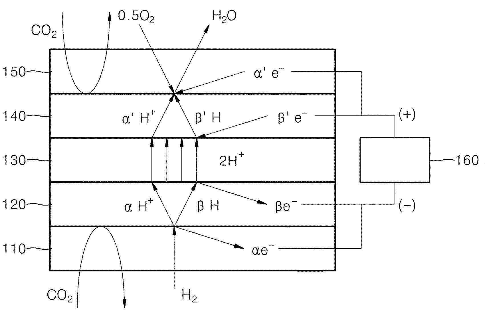
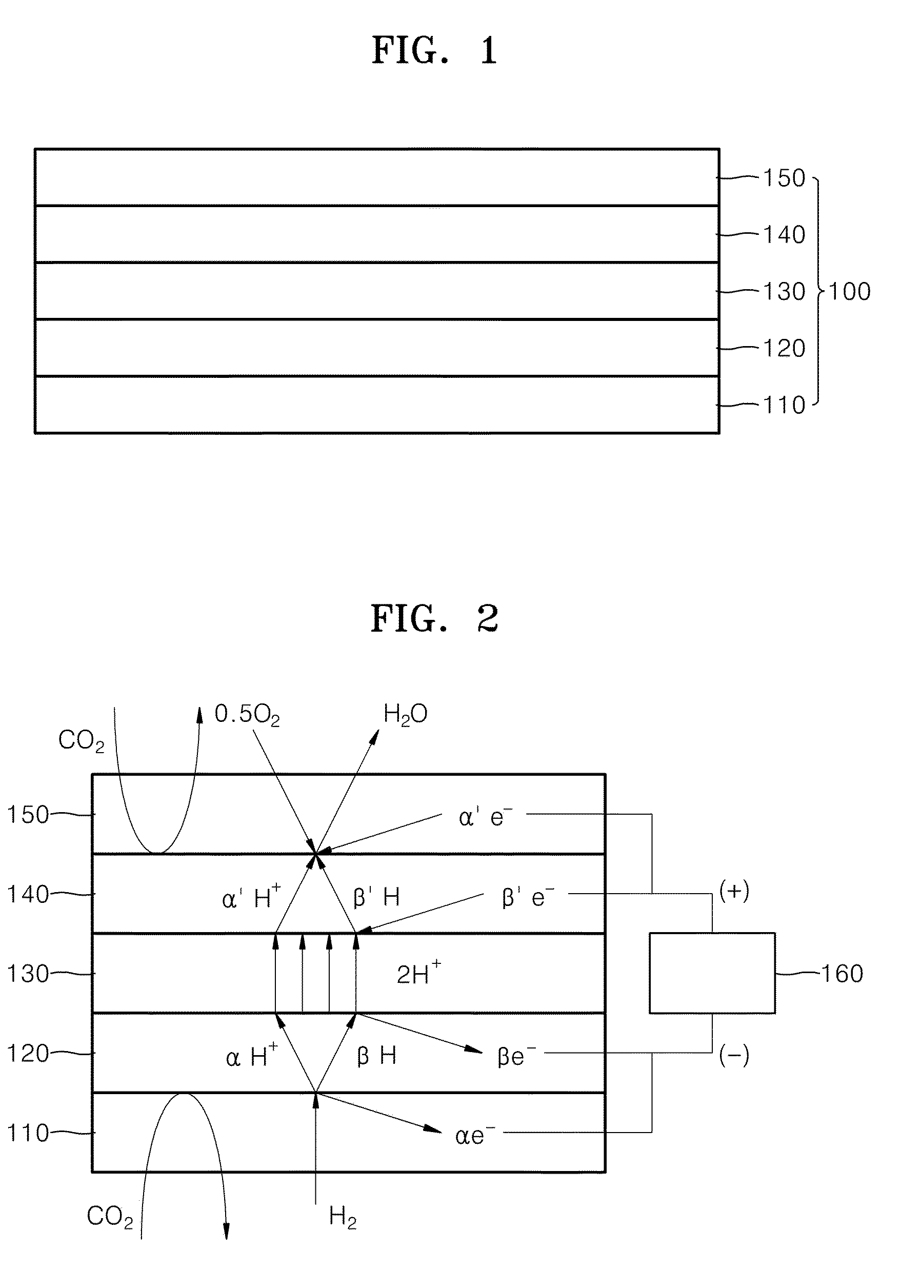
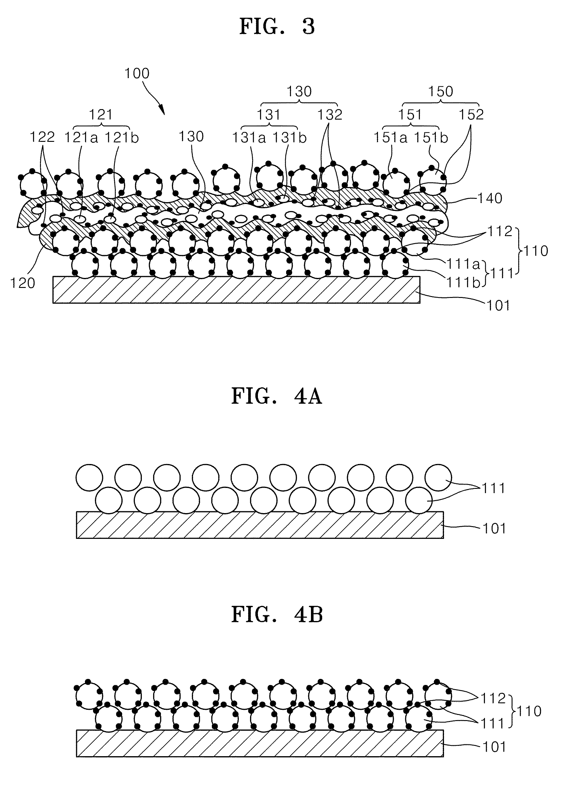
A solid-state fuel cell includes: an anode; an anode side chemical electrolyte protection layer disposed on the anode; a hydrogen ion conductive solid oxide film disposed on the anode side chemical electrolyte protection layer; a cathode side chemical electrolyte protection layer disposed on the hydrogen ion conductive solid oxide film; and a cathode disposed on the cathode side chemical electrolyte protection layer.

Description

BACKGROUND[0001]1. Field[0002]One or more embodiments relate to a solid-state fuel cell and a method of manufacturing the same, and more particularly, to a solid-state fuel cell including a chemical electrolyte protection layer and a method of manufacturing the same.[0003]2. Description of the Related Art[0004]It is desirable for a fuel cell to secure high energy conversion efficiency and price competency. In order to support anode and cathode reactions, catalysts are respectively included in the anode and the cathode of the fuel cell. In such fuel cells, if the temperature is increased, more electrochemical reaction may occur, even if the amount of catalysts remains the same. Thus, a lesser amount of catalyst is needed for a fuel cell that operates at a higher temperature, thereby improving price competency. On the other hand, in a polymer electrolyte fuel cell, an electrolyte membrane should be hydrated to obtain ionic conductivity. Accordingly, in order to avoid dehydration of th...

Claims


Application Information

Patent Timeline
Patent Type & Authority Applications(United States)
IPC IPC(8): H01M8/10
CPCH01M4/8663H01M8/1213Y02E60/521H01M2008/1293Y02E60/525H01M4/8657Y10T29/49115H01M2300/0074Y02P70/56
Inventor KANG, SANGKYUNSHIM, JOONHYUNGPRINZ, FRIEDRICH B.GOR, TURUOT M.
Owner SAMSUNG ELECTRONICS CO LTD
Learn More