
Fuel cell system capable of reducing electric power loss

Inactive Publication Date: 2001-07-03
TOYOTA JIDOSHA KK
View PDF7 Cites 178 Cited by
  • Summary
  • Abstract
  • Description
  • Claims
  • Application Information

AI Technical Summary

Benefits of technology

In the invention, if the switch device is switched so that the power generated by the fuel cell is supplied to the load via the bypass device, the power supply from the fuel cell to the load bypasses the voltage adjusting device, so that substantially no power loss occurs in the conduction passage.
In a case where it is unnecessary to store power into the secondary battery or output power from the secondary battery, the electric connection between the secondary battery and the bypass device and the electric connection between the secondary battery and the load may be discontinued by using a shutting device in such a manner that the secondary battery is completely electrically disconnected from the load, the fuel cell and the like. The electrical disconnection of the secondary battery in this manner does not cause any substantial problem. When the secondary battery is thus disconnected, it becomes unnecessary to set the output voltage of the second battery to a desired value, so that the voltage adjusting device becomes unnecessary in this case. Therefore, the power generated by the fuel cell can be supplied to the load via the bypass device by using the switch device, without causing any problem. Hence, substantially no power loss occurs in the conduction passage.

Problems solved by technology

When the secondary battery is thus disconnected, it becomes unnecessary to set the output voltage of the second battery to a desired value, so that the voltage adjusting device becomes unnecessary in this case.

Method used


Image

  • Fuel cell system capable of reducing electric power loss
  • Fuel cell system capable of reducing electric power loss
  • Fuel cell system capable of reducing electric power loss

Examples


Embodiment Construction

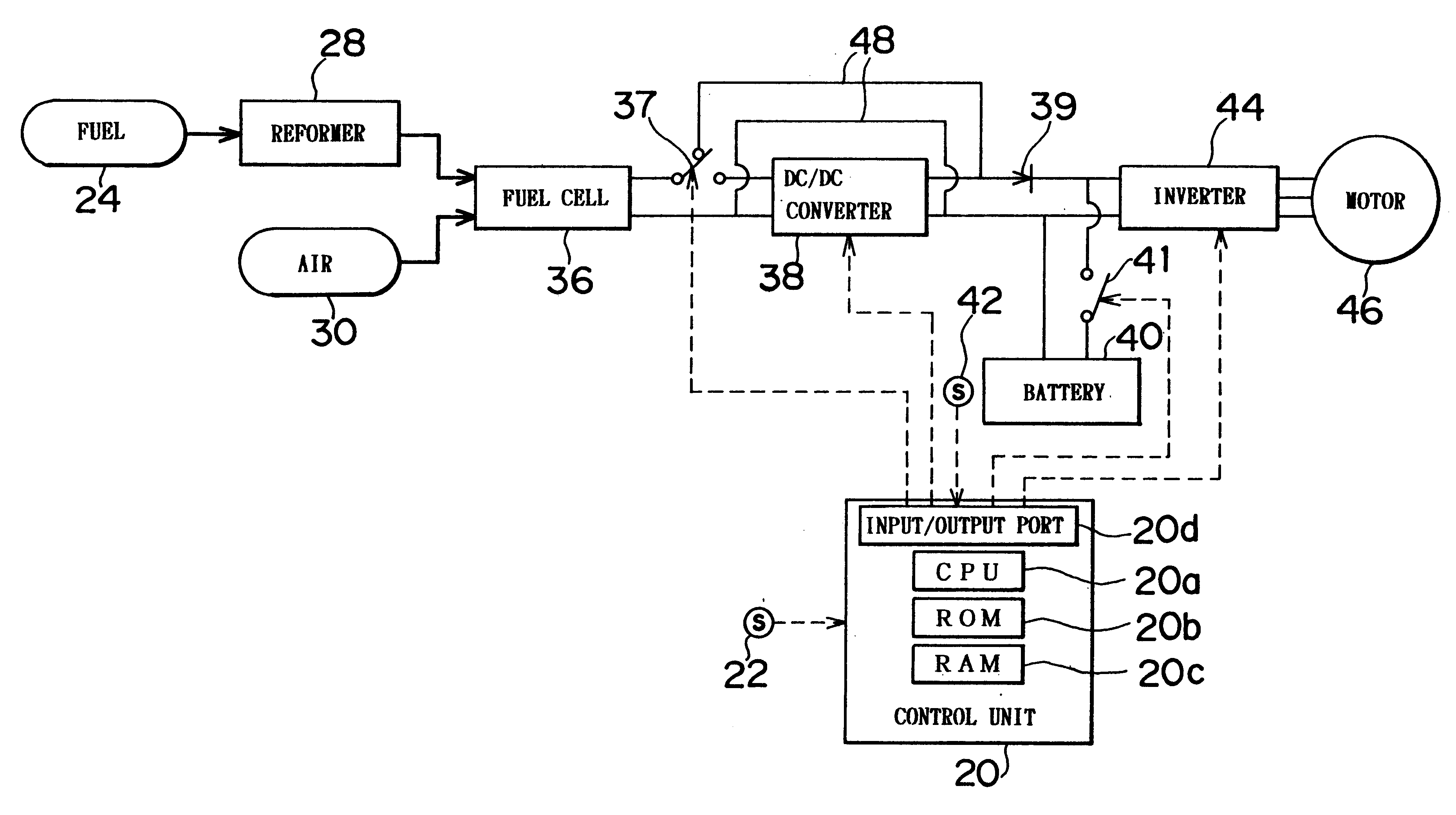
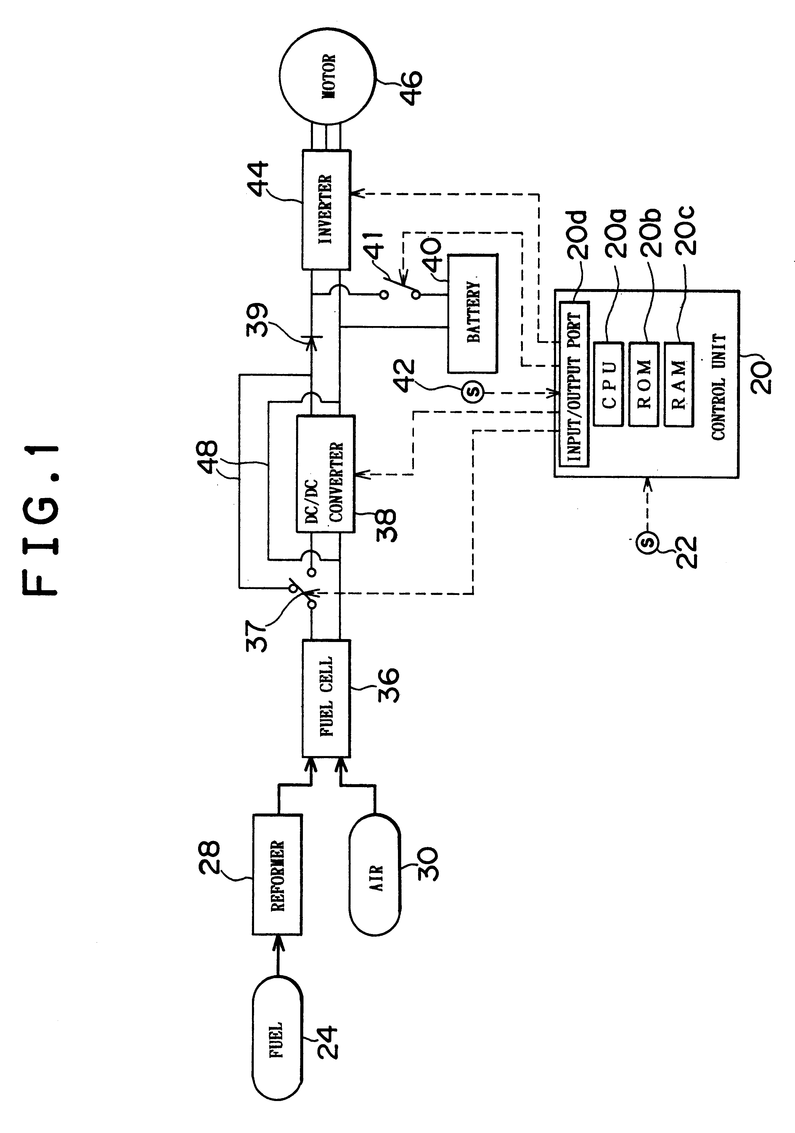
A preferred embodiment of the present invention will be described in detail hereinafter with reference to the accompanying drawings. FIG. 1 is an illustration of the construction of a fuel cell system according to an embodiment of the invention. The fuel cell system of the embodiment may be installed in an electric vehicle.

The construction of the fuel cell system illustrated in FIG. 1 and overall operation thereof will be described. The fuel cell system shown in FIG. 1 has, as main components, a control unit 20, an accelerator pedal position sensor 22, a reformer 28, a fuel cell 36, a changeover switch 37, a DC / DC converter 38, a diode 39, a battery 40, a cutoff switch 41, a state-of-charge (SOC) sensor 42, an inverter 44, a motor 46, and a bypass 48.

The reformer 28 is supplied with a fuel 24, such as methanol and water and the like, and produces a hydrogen-rich gas (reformed gas) containing hydrogen through a steam reforming reaction with methanol as expressed by equation (1):

CH.su...


PUM

PropertyMeasurementUnit
poweraaaaaaaaaa
voltageaaaaaaaaaa
electric power lossaaaaaaaaaa

Abstract

A fuel cell system minimizes the power loss that may occur in a conduction passage during supply of electric power from a fuel cell to a load. A bypass connects between the input of a DC / DC converter and the output thereof, and therefore supplies power generated by the fuel cell to an inverter, bypassing the DC / DC converter. A changeover switch selectively changes the connection of the output of the fuel cell between the connection to the input of the DC / DC converter and the connection to the bypass. When the fuel cell is connected to the DC / DC converter, the power from the fuel cell is supplied to the inverter or a battery via the DC / DC converter. When the fuel cell is connected to the bypass, the power from the fuel cell is supplied to the inverter, bypassing the DC / DC converter. A cutoff switch disconnects the output of the battery from a connecting line. That is, the cutoff switch disconnects the battery from the inverter, the bypass and the like when turned off. When turned on, the cutoff switch 41 connects the battery to those components.

Description

INCORPORATION BY REFERENCEThe disclosure of Japanese Patent Application No. HEI 10-219648 filed on Jul. 16, 1998 including the specification, drawings and abstract is incorporated herein by reference in its entirety.1. Field of the InventionThe present invention relates to a fuel cell system capable of reducing electric power loss in a power conducting passage for supplying power from a fuel cell to a load.2. Description of the Related ArtA conventional fuel cell system installable in an electric vehicle is constructed as illustrated in FIG. 5. A fuel 124, such as water and methanol and the like, is supplied into a reformer 128. The reformer 128 produces a fuel gas, such as hydrogen gas, from the fuel 124 through steam reforming reaction with methanol. The fuel gas produced by the reformer 128 and air 130 are supplied into a fuel cell 136. The fuel cell 136 generates an electromotive force through electrochemical reactions. The generated electric power is supplied from the fuel cell...

Claims


Application Information

Patent Timeline
Patent Type & Authority Patents(United States)
IPC IPC(8): B60L11/18H01M8/00H02J7/34
CPCB60L11/1881Y02T90/34Y02T10/7216B60L2210/10B60L58/30Y02T10/72Y02T90/40
Inventor IWASE, MASAYOSHI
Owner TOYOTA JIDOSHA KK
Learn More