
Power management system for vehicles

a technology for power management and vehicles, applied in the direction of electric variable regulation, process and machine control, instruments, etc., can solve the problems of battery degradation, reducing its useful life, and relatively uncontrolled charging and discharging of batteries

Inactive Publication Date: 2006-06-06
VANNER
View PDF19 Cites 105 Cited by
  • Summary
  • Abstract
  • Description
  • Claims
  • Application Information

AI Technical Summary

Problems solved by technology

Firstly, the alternator must operate at a voltage compatible with the battery, even if most of the power provided by the alternator is consumed by a load that is configured to optimally operate at a different supply voltage.
In addition, the battery voltage is necessarily the same as the distribution bus voltage regardless of the battery's temperature or state of charge, causing degradation of the battery and reducing its useful life.
Further, the charging and discharging of the battery is relatively uncontrolled.
However, inverters suffer from a limitation in that their output power, measured in volt-amps (“VA”) or watts, may be constrained under some conditions.
For example, an inverter that derives its input power from a vehicle's alternator system may not be able to deliver the full amount of electrical power demanded by a load when the vehicle is at idle since the power delivery capacity of an alternator varies directly with the vehicle's engine speed.

Method used


Image

  • Power management system for vehicles
  • Power management system for vehicles
  • Power management system for vehicles

Examples


Embodiment Construction

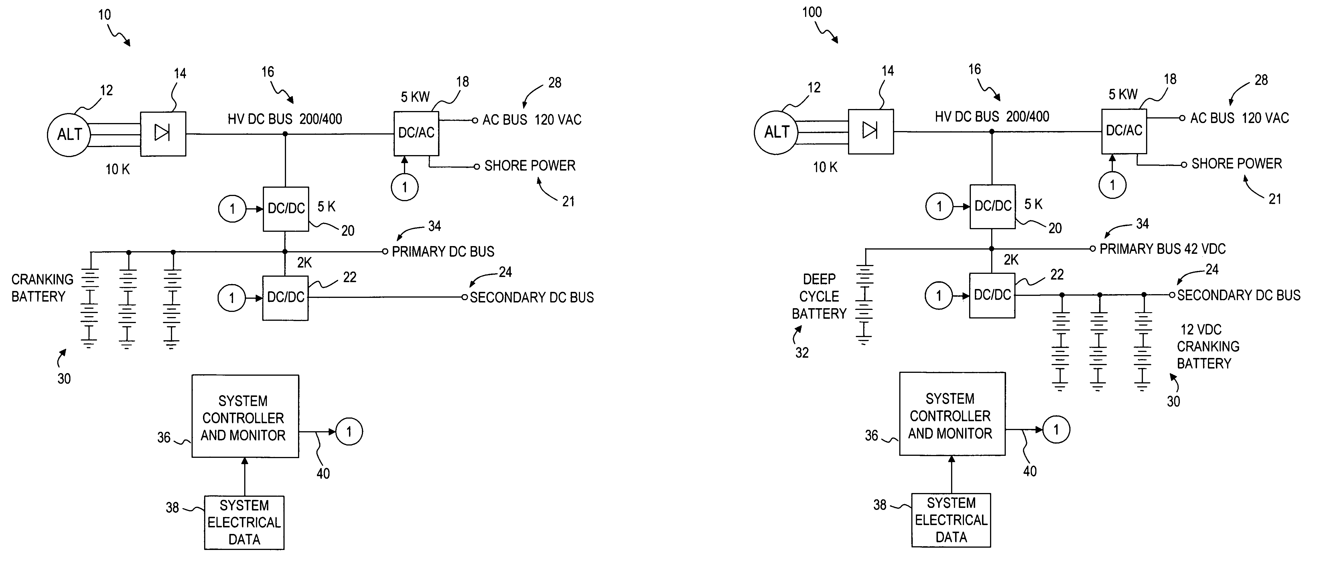
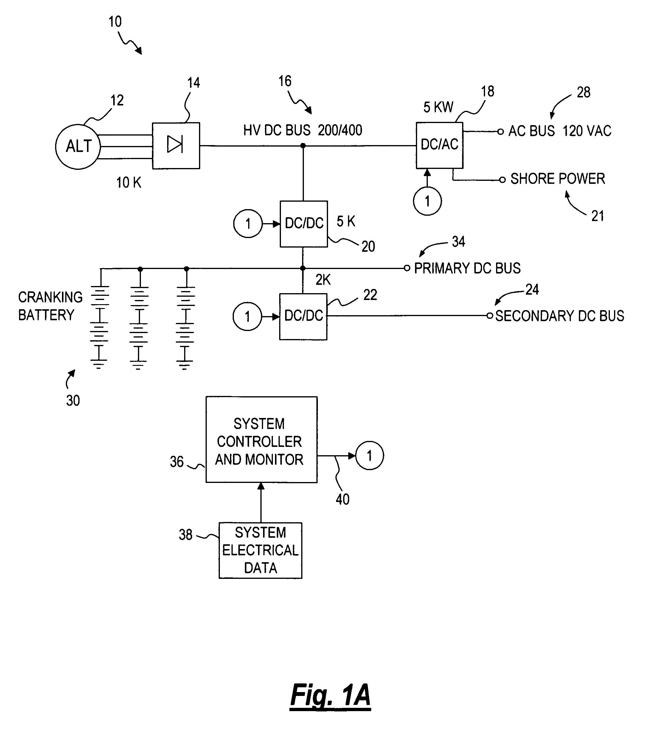
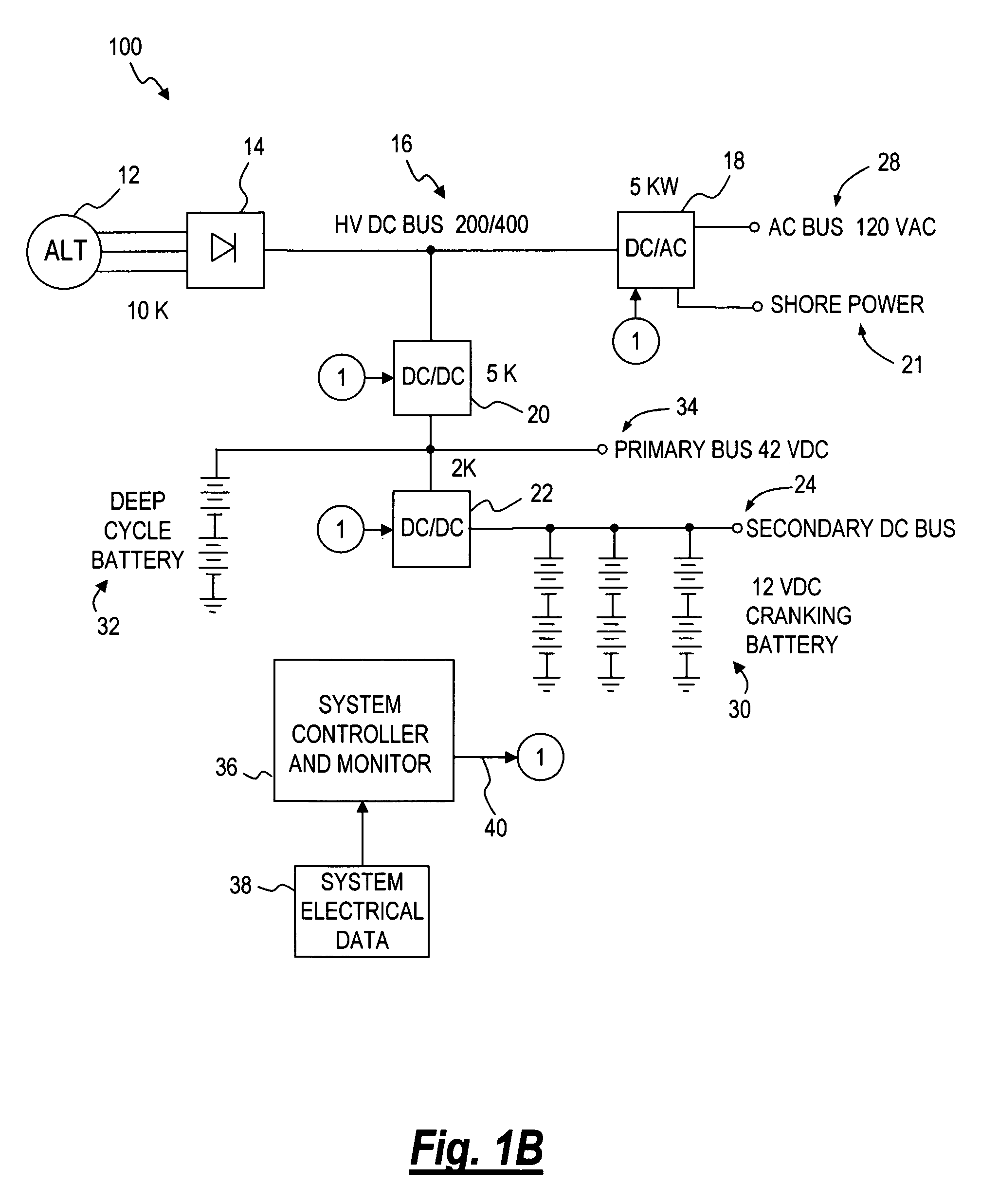
[0024]In the discussion that follows and in the accompanying figures, like reference numerals are used to indicate components having substantially the same structure or function. In addition, in the figures, a numeral within a circle indicates a common point of connection for an attached structure or functional block. For example, each component in a figure having a connection to or from an encircled (1) are logically and / or electrically connected together.

[0025]The present invention comprises varying configurations of a vehicle power management system as discussed below and shown in the accompanying figures. The preferred configuration of the power management system for a particular vehicle depends upon the type and quantity of input power available and the output power requirements for the vehicle.

[0026]With reference to FIG. 1A, an improved power management system 10 is depicted according to an embodiment of the present invention. High-voltage AC generated by an alternator 12 is ...


PUM


Abstract

A power management system for a vehicle. The system may be flexibly configured using various arrangements of DC to AC inverters, DC to DC converters AC to DC converters, DC to AC converters and AC to AC converters, one or more batteries, and a control portion to provide an AC bus, a primary DC bus and a secondary DC bus. The control portion monitors the status of the buses, inverters and converters and controls the operation of the inverters and converters to supply and regulate the power supplied by the buses. The inverters and converters may be bidirectional, allowing power to be transferred between buses.

Description

[0001]This application claims priority to U.S. provisional application 60 / 536,328, filed Jan. 14, 2004, the contents of which are hereby incorporated by reference.FIELD[0002]This invention relates to a system for providing and controlling electric power. In particular, this invention relates to power management of a vehicle electrical power system.BACKGROUND[0003]A typical vehicle power system consists of a battery, an alternator to charge the battery and to augment power supplied by the battery, and one or more distribution buses to power a variety of loads connected to the system. In such arrangements there is usually only a single degree of control wherein the field voltage of the alternator is controlled to regulate the output of the alternator and in turn regulate the voltage of the power distribution bus, which is usually on the order of about 14 volts DC or 28 volts DC. This has two primary effects. Firstly, the alternator must operate at a voltage compatible with the battery...

Claims


Application Information

Patent Timeline
Patent Type & Authority Patents(United States)
IPC IPC(8): G05F1/70H02M1/12
CPCB60R16/03H02J1/08H02J4/00H02J1/102H02J2001/008H02J1/082H02J2310/46
Inventor COOK, ALEXANDERISURIN, ALEXANDERIRWIN, PHILIP WARWICK
Owner VANNER
Learn More