
High temperature, high efficiency thermoelectric module

a thermoelectric module, high-efficiency technology, applied in the direction of thermoelectric device junction materials, thermoelectric device manufacture/treatment, electrical apparatus, etc., can solve the problems of mica, marginal strength, easy cracking, and low thermoelectric efficiency, so as to reduce thermal conductivity, increase zt, and prevent grain growth

Inactive Publication Date: 2010-09-16
HI Z TECH +1
View PDF12 Cites 47 Cited by
  • Summary
  • Abstract
  • Description
  • Claims
  • Application Information

AI Technical Summary

Benefits of technology

[0021]The present invention provides a long life, low cost, high-temperature, high efficiency thermoelectric module. Preferred embodiments include a two-part (a high temperature part and a low temperature part) egg-crate and segmented N legs and P legs. In preferred embodiments the legs are segmented into two or three segments. In preferred embodiments three segments are chosen for their chemical compatibility and / or their figure of merit in the various temperature ranges between the hot side and the cold side of the module. The legs include metal meshes partially embedded in thermoelectric segments to help maintain electrical contacts notwithstanding substantial differences in thermal expansions. In preferred embodiments a two-part molded egg-crate holds in place and provides insulation and electrical connections for the thermoelectric N legs and P legs. The high temperature part of the egg-crate is comprised of a ceramic material capable of operation at temperatures in excess of 500° C. and the low temperature part is comprised of a liquid crystal polymer material having very low thermal conductivity. In preferred embodiments the high temperature ceramic is zirconium oxide and the liquid crystal polymer material is a DuPont Zenite available from DuPont in the form of a liquid crystal polymer resin. Preferably the module is sealed in an insulating capsule.
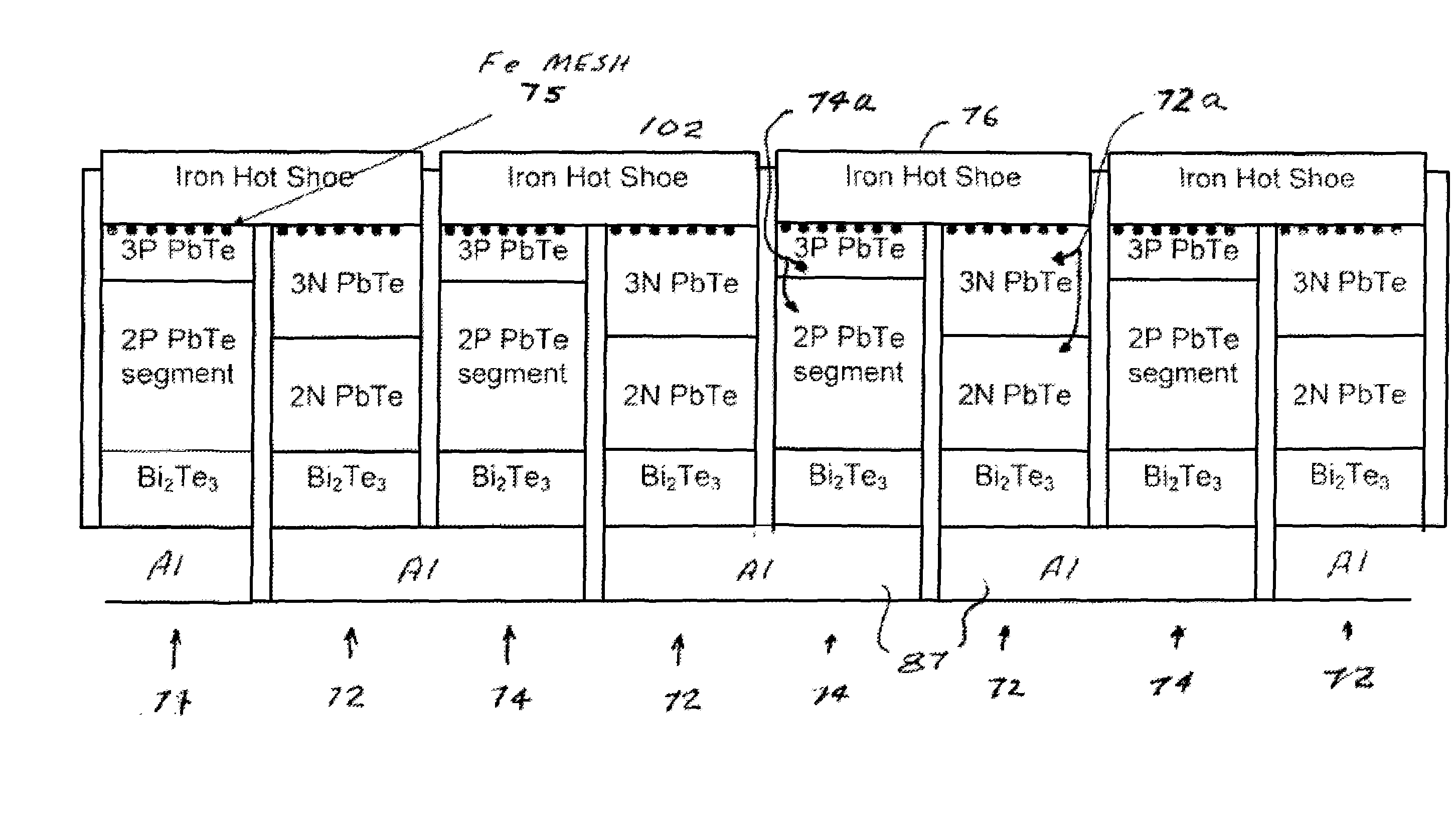
[0022]In preferred embodiments the high and intermediate temperature thermoelectric materials for the N legs are two types of lead telluride thermoelectric material (3N and 2N, respectively) and the low-temperature material is bismuth telluride. The high and intermediate temperature materials for the P legs are also lead telluride (3P and 2P, respectively). And the low temperature material is bismuth telluride. In preferred embodiments low temperature contacts are provided by thermally sprayed molybdenum-aluminum which provides excellent electrical contacts between the N and P legs. Iron metal mesh spacers are provided at the hot side to maintain electrical contact notwithstanding substantial thermal expansion variations. These mesh spacers may also be inserted between the lead telluride material and the bismuth telluride and / or between the different types of lead telluride material. These mesh spacers are flexible and maintain good contact and prevent or minimize cracking in the legs despite the expansion and contraction of the legs due to thermal cycling.Module with Sixteen Percent Efficiency
[0025]With a Bi2Te3 segment on the cold side of the PbTe leg it is possible to use Applicants' employer's standard prior art Bi2Te3 contacting methods as described in U.S. Pat. No. 5,856,200, especially FIGS. 19A and 19B and related text, which is incorporated by reference herein. This is a method of forming contacts to Bi2Te3 using thermal spraying of molybdenum and aluminum. The resultant cold side contact is firmly bonded to the legs and eliminates the need for numerous individual components. Instead of molybdenum and aluminum zinc may also be used.Hot Side
[0026]Applicants have embedded iron mesh contacts into the PbTe to make a compliant thermal and electrical connection to an iron connector. This has several advantages. By embedding an iron mesh (or other compatible material) into PbTe the surface area of the contact can be much larger than the simple prior art planar contact of an iron shoe. In addition to the larger contact area, an embedded contact is held in place by mechanical forces as well as a metallurgical bond. The iron mesh is spot welded to the iron shoe. These metal meshes permit the modules to be utilized without the normally required compression between the hot and cold surfaces.Hot Side Segment Compatibility with Iron Shoe
[0028]A significant amount of work has been recently performed to create nano-sized thermoelectric material. Nano-sized materials have a large number of grain boundaries that impede the propagation of phonons through the material resulting in reduced thermal conductivity and increased ZT. To ensure a nano-sized structure, an inert fine material is added to the alloy that is in the form of nano-sized particulates. The fine additive results in prevention of grain growth and also impedes phonon propagation. This technique has been used with P type Bi2Te3 alloys. Applicants have demonstrated that similar reductions in thermal conductivity can be achievable in PbTe by fabricating it with nano-sized grains. Nano-sized grains can be achieved by ball milling, mechanical alloying, chemical processing and other techniques. Applicants have added nano-size alumina powder to nano-sized PbTe powder. These experiments indicated increased efficiencies and successfully inhibited grain growth at 800° C. This approach mimics the commercial oxide dispersion strengthened (ODS) alloys in which the micron sized oxides are added to prevent grain growth, greatly reduces creep and increases strength.

Problems solved by technology

The reason primarily is that thermoelectric efficiencies are typically low compared to other technologies for electric power generation and the cost of thermoelectric systems per watt generated is high relative to other power generating sources.
Mica, however, is marginal in strength and cracks easily.
That lead telluride module was suited for operation in temperature ranges in excess of 500° C. But the cost of fabrication of this prior art module is greatly in excess of the bismuth telluride module described above.
Also, after a period of operation of about 1000 hours some evaporation of the P legs and the N legs at the hot side would produce cross contamination of all of the legs which would result in degraded performance.

Method used


Image

  • High temperature, high efficiency thermoelectric module
  • High temperature, high efficiency thermoelectric module
  • High temperature, high efficiency thermoelectric module

Examples


first preferred embodiment

[0040]A first preferred embodiment of the present invention can be described by reference to FIGS. 4, 4A and 7. The FIGS. 4 and 4A drawings are from the parent application Ser. No. 12 / 317,170, but this first preferred module is substantially improved and more efficient version than the embodiment described in parent patent application which has been incorporated herein by reference. For example one significant difference is that the first preferred embodiment in this application utilizes three-segment thermoelectric legs in the module instead of only two. Specifically, for this preferred embodiment segments 72a and 74a as shown in FIGS. 4 and 4A are each comprised of two types of lead telluride material instead of only one type as in the parent application. This preferred embodiment is shown more specifically in FIG. 7 where the two types of lead telluride material in each leg are clearly shown. Details regarding the legs are provided below in the section entitled “Three Segment The...


PUM

PropertyMeasurementUnit
temperaturesaaaaaaaaaa
temperatureaaaaaaaaaa

Abstract

A long life, low cost, high-temperature, high efficiency thermoelectric module. Preferred embodiments include a two-part (a high temperature part and a cold temperature part) egg-crate and segmented N legs and P legs, with the thermoelectric materials in the three segments chosen for their chemical compatibility or their figure of merit in the various temperature ranges between the hot side and the cold side of the module. The legs include metal meshes partially embedded in thermoelectric segments to help maintain electrical contacts notwithstanding substantial temperature variations. In preferred embodiments a two-part molded egg-crate holds in place and provides insulation and electrical connections for the thermoelectric N legs and P legs. The high temperature part of the egg-crate is comprised of a ceramic material capable of operation at temperatures in excess of 500° C. and the cold temperature part is comprised of a thermoplastic material having very low thermal conductivity.

Description

CROSS REFERENCE TO RELATED APPLICATIONS[0001]The present invention is a continuation-in-part of Ser. No. 12 / 317,170 filed Dec. 19, 2008.FIELD OF THE INVENTION[0002]The present invention relates to thermoelectric modules and especially to high temperature thermoelectric modules.BACKGROUND OF THE INVENTIONThermoelectric Materials[0003]The Seebeck coefficient of a thermoelectric material is defined as the open circuit voltage produced between two points on a conductor, where a uniform temperature difference of 1 K exists between those points.[0004]The figure-of-merit of a thermoelectric material is defined as:Z=α2σλ,where α is the Seebeck coefficient of the material, σ is the electrical conductivity of the material and λ is the total thermal conductivity of the material.[0005]A large number of semiconductor materials were being investigated by the late 1950's and early 1960's, several of which emerged with Z values significantly higher than in metals or metal alloys. As expected no sin...

Claims


Application Information

Patent Timeline
Patent Type & Authority Applications(United States)
IPC IPC(8): H01L35/20
CPCH01L35/16H01L35/34H01L35/32H10N10/852H10N10/01H10N10/17H10N10/80
Inventor LEAVITT, FREDERICK A.ELSNER, NORBERT B.BASS, JOHN C.MCCOY, JOHN W.
Owner HI Z TECH
Learn More