Water electrolysis system and method of shutting down water electrolysis system

Active Publication Date: 2010-08-19
HONDA MOTOR CO LTD
View PDF2 Cites 26 Cited by
  • Summary
  • Abstract
  • Description
  • Claims
  • Application Information

AI Technical Summary

Benefits of technology

[0016]It is an object of the present invention to provide a water electrolysis system and a method of shutting down such a water electrolysis system, which are capable of minimizing the amount of high-pressure hydrogen to be wasted that exists downstream of a water electrolysis apparatus when the water electrolysis apparatus, which generates high-pressure hydrogen, is depressurized to a normal pressure, for thereby performing a water electrolysis process efficiently and economically.
[0020]Therefore, the high-pressure hydrogen processing apparatus, which contains a relatively large amount of high-pressure hydrogen therein, does not need to be depressurized, and any amount of high-pressure hydrogen which would otherwise be wasted is minimized. Consequently, the water electrolysis system can electrolyze water efficiently and economically.
[0021]In addition, for resuming the water electrolysis system, only a minimum volume required, i.e., the water electrolysis apparatus, needs to be pressurized because the high-pressure hydrogen processing apparatus is kept under high pressure. Therefore, the power consumption at the time the water electrolysis system is resumed is kept low, the water electrolysis system can be resumed quickly, and its efficiency is easily increased.

Problems solved by technology

This is because if the solid polymer electrolyte membrane is maintained under a differential pressure at all times, then the solid polymer electrolyte membrane is susceptible to damage.
Since the high-pressure hydrogen remaining in the high-pressure line is depressurized, the depressurized high-pressure hydrogen is wasted.
Therefore, the water electrolysis system is uneconomical.
In addition, when the water electrolysis system is to be resumed, it takes a considerable time to pressurize the high-pressure hydrogen line downstream of the water electrolysis apparatus, i.e., to fill the high-pressure hydrogen line downstream of the water electrolysis apparatus with high-pressure hydrogen.
Consequently, the resumption of the water electrolysis process requires an increase in the power consumption, is time-consuming and hence is not efficient.

Method used


Image

  • Water electrolysis system and method of shutting down water electrolysis system
  • Water electrolysis system and method of shutting down water electrolysis system
  • Water electrolysis system and method of shutting down water electrolysis system

Examples


first embodiment

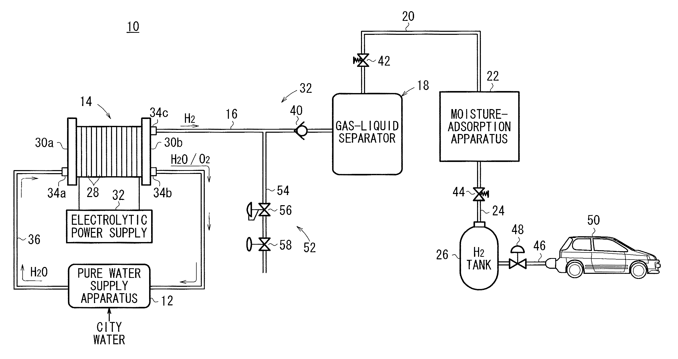
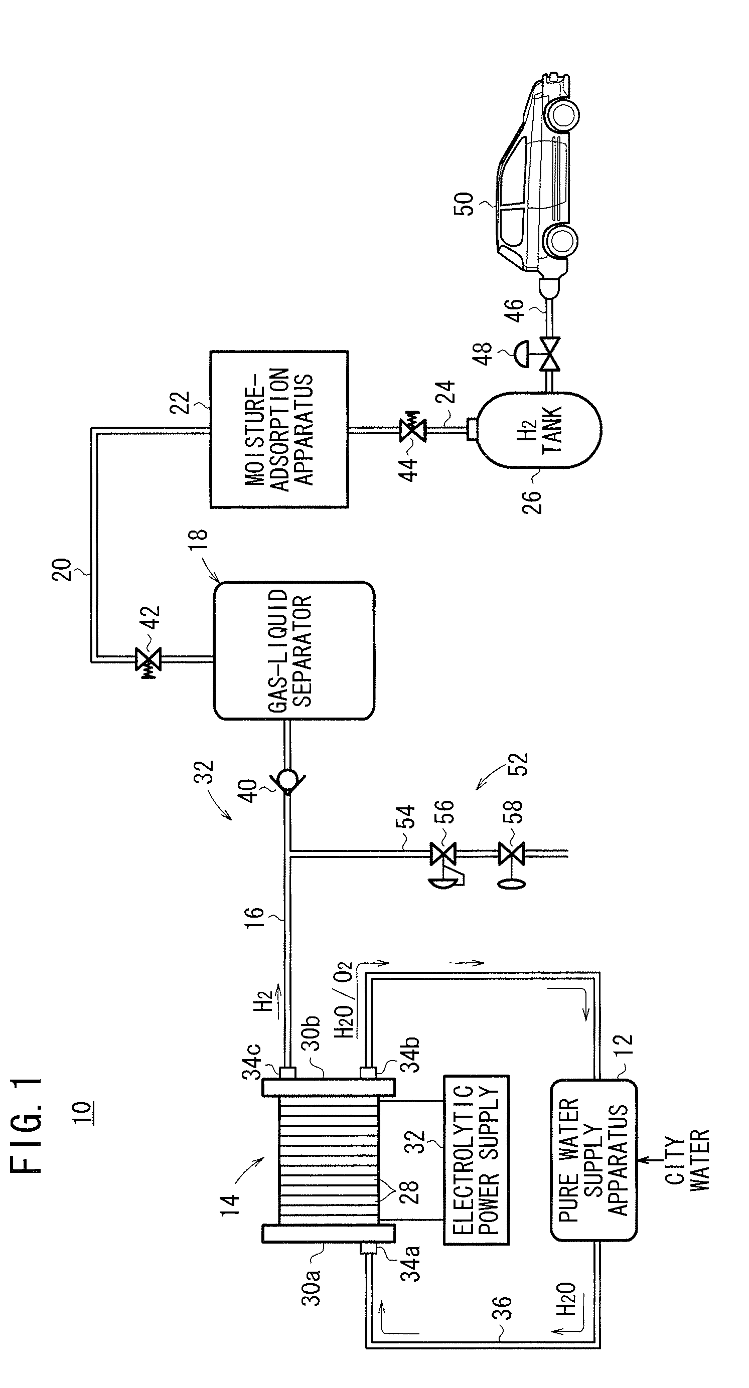
[0031]As shown in FIG. 1, a water electrolysis system 10 to which a system shutdown method according to the present invention is applied comprises a water electrolysis apparatus 14 for being supplied with pure water that has been generated from city water from a pure water supply apparatus 12 and electrolyzing the pure water to produce high-pressure hydrogen (whose pressure is higher than a normal pressure), a gas-liquid separator (high-pressure hydrogen processing apparatus) 18 for removing moisture contained in the high-pressure hydrogen delivered from the water electrolysis apparatus 14 into a hydrogen outlet passage 16, a moisture-adsorption apparatus (high-pressure hydrogen processing apparatus) 22 for adsorbing and eliminating moisture contained in hydrogen delivered from the gas-liquid separator 18 into a hydrogen supply passage 20, and a hydrogen tank 26 for storing the hydrogen (dry hydrogen) that is delivered out to a dry hydrogen supply passage 24 connected to the moistur...

second embodiment

[0054]FIG. 5 schematically shows a water electrolysis system 60 according to the present invention.

[0055]Those parts of the water electrolysis system 60 which are identical to those of the water electrolysis system 10 according to the first embodiment are denoted by identical reference characters, and will not be described in detail below.

[0056]As shown in FIG. 5, the water electrolysis system 60 includes a pressure releasing device 62 connected to the hydrogen outlet passage 16 between the pipe 34c and the check valve 40. The pressure releasing device 62 has a function to release the hydrogen pressure in the water electrolysis apparatus 14 independently from the gas-liquid separator 18 and other components connected downstream thereof. The pressure releasing device 62 comprises a needle valve 64 and a solenoid-operated valve 58 which are connected to a bleeder passage 54 connected to the hydrogen outlet passage 16.

[0057]According to the second embodiment, the needle valve 64 is emp...

third embodiment

[0058]FIG. 6 schematically shows a water electrolysis system 70 according to the present invention.

[0059]Those parts of the water electrolysis system 70 which are identical to those of the water electrolysis system 10 according to the first embodiment are denoted by identical reference characters, and will not be described in detail below.

[0060]As shown in FIG. 6, the water electrolysis system 70 includes a pressure releasing device 72 connected to the hydrogen outlet passage 16 between the pipe 34c and the check valve 40. The pressure releasing device 72 has a function to release the hydrogen pressure in the water electrolysis apparatus 14 independently from the gas-liquid separator 18 and other components connected downstream thereof. The pressure releasing device 72 comprises a mass flow controller (MFC) 74 and is free of the solenoid-operated valve.

[0061]The mass flow controller 74 is capable of lowering the pressure of the high-pressure hydrogen from the water electrolysis appa...


PUM

PropertyMeasurementUnit
Pressureaaaaaaaaaa

Abstract

A water electrolysis system includes a water electrolysis apparatus for electrolyzing pure water supplied from a pure water supply apparatus to produce high-pressure hydrogen. A pressure releasing device is connected between a pipe of the water electrolysis apparatus and a check valve connected to the inlet port of a gas-liquid separator, for releasing the pressure of the high-pressure hydrogen from the water electrolysis apparatus independently from the gas-liquid separator. The pressure releasing device has a bleeder passage including a pressure reducing valve and a solenoid-operated valve.

Description

CROSS-REFERENCE TO RELATED APPLICATION[0001]This application is based upon and claims the benefit of priority from Patent Application No. 2009-036417 filed on Feb. 19, 2009, in the Japan Patent Office, of which the contents are incorporated herein by reference.BACKGROUND OF THE INVENTION[0002]1. Field of the Invention[0003]The present invention relates to a water electrolysis system having a water electrolysis apparatus for electrolyzing water with an electric current supplied from a DC power supply to generate hydrogen and oxygen and a high-pressure hydrogen processing apparatus disposed downstream of and connected to a hydrogen outlet of the water electrolysis apparatus, for refining high-pressure hydrogen discharged from the hydrogen outlet which discharges hydrogen under a pressure higher than a normal pressure, and a method of shutting down such a water electrolysis system.[0004]2. Description of the Related Art[0005]Solid polymer electrolyte fuel cells generate DC electric ene...

Claims


Application Information

Patent Timeline
IPC IPC(8): C25B15/00C25B9/00C25B1/04
CPCC25B1/04Y02E60/366C25B15/08Y02E60/36
Inventor TAKEUCHI, JUNOKABE, MASANORINAKAZAWA, KOJITARUYA, KENJI
Owner HONDA MOTOR CO LTD
Why Eureka
Try Eureka