Functional graphene-rubber nanocomposites
a technology of functional graphene and nanocomposites, which is applied in the direction of non-metal conductors, conductors, transportation and packaging, etc., can solve the problems of insufficient nanoparticle dispersion, easy outpacing earlier attempts, and unparallel performance improvement, so as to improve mechanical (strength, toughness, modulus) and thermal stability, and improve the electrical conductivity of the rubber composite
- Summary
- Abstract
- Description
- Claims
- Application Information
AI Technical Summary
Benefits of technology
Problems solved by technology
Method used
Image
Examples
example 1
[0189]Graphite oxide was prepared from graphite by a process of oxidation and intercalation, referred to as the Staudenmaier method. The method uses a combination of oxidizers and intercalants: sulfuric acid, nitric acid and potassium chlorate under controlled temperature conditions. Ratios of graphite to potassium chlorate in the range of 1:8 to 1:20 (wt / wt) are preferred. Ratios of sulfuric to nitric acid from 5:1 to 1:1 are preferred. The Staudenmaier method is the preferred oxidation procedure.
[0190]In this example, 5 g graphite flake with a 400 μm average flake size (Asbury Carbon, Asbury, N.J.) was added to an ice-cooled solution containing 85 ml sulfuric acid and 45 ml nitric acid. This was followed by the addition of 55 g potassium chlorate over 20 minutes such that the temperature did not exceed 20° C. After this oxidation / intercalation process proceeded for 96 hours, the reaction mixture was poured into 7 l of deionized water and filtered using an aspirator. The oxidized g...
example 2
[0191]In preparing functional graphene (FGS), graphite oxide (0.2 g) was placed in a ceramic boat and inserted into a 25 mm ID, 1.3 m long quartz tube that was sealed at one end. The other end of the quartz tube was closed using a rubber stopper. An argon (Ar) inlet and thermocouple were then inserted through the rubber stopper. The sample was flushed with Ar for 10 minutes; the quartz tube was then quickly inserted into a preheated Lindberg tube furnace and heated for 30 seconds.
example 3
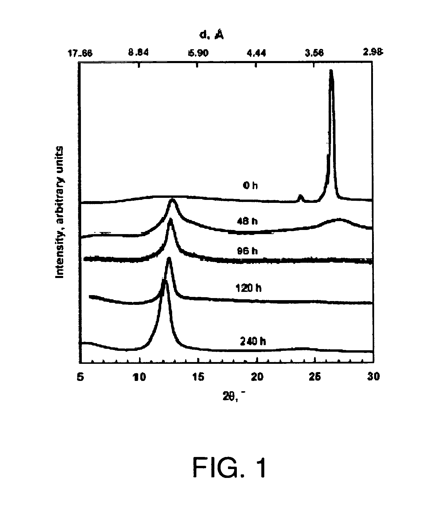
[0192]XRD patterns of graphite, GO, and FGS were recorded in a Rigaku MiniFlex diffractometer with Cu Kα radiation. Initial, final and step angles were 5, 30 and 0.02, respectively. The surface area of FGS was measured by nitrogen adsorption at 77K using a Micromeritics FlowSorb apparatus with a mixture of N2 and He 30 / 70 by volume as the carrier gas. High-resolution XPS spectra were obtained using an Omicron ESCA Probe (Germany). Samples were de-gassed overnight within the XPS chamber (10-3 mbar) prior to analysis of the sample. Data were collected using 15 kV and 20 mA power at 10-9 mbar vacuum. The raw XPS data were analyzed to determine peak locations and areas in relation to specific binding energies that best fit the experimental data. The main C—C peak (C1s) at 284.6 eV was observed. An additional photoemission present at higher binding energy peaks at 286.1 eV represented —C—O— or C—O—C bonding.
PUM
| Property | Measurement | Unit |
|---|---|---|
| Percent by mass | aaaaa | aaaaa |
| Density | aaaaa | aaaaa |
| Specific surface area | aaaaa | aaaaa |
Abstract
Description
Claims
Application Information
 - R&D
- Intellectual Property
- Life Sciences
- Materials
- Tech Scout
- Unparalleled Data Quality
- Higher Quality Content
- 60% Fewer Hallucinations
Browse by: Latest US Patents, China's latest patents, Technical Efficacy Thesaurus, Application Domain, Technology Topic, Popular Technical Reports.
© 2025 PatSnap. All rights reserved.Legal|Privacy policy|Modern Slavery Act Transparency Statement|Sitemap|About US| Contact US: help@patsnap.com


