
Material for Laser Welding

a laser welding and material technology, applied in the direction of machines/engines, synthetic resin layered products, combustion air/fuel air treatment, etc., can solve the problems of insufficient heat-melting at the joining interface between the non-transmissive resin material and the transmissive resin material, the inability to achieve satisfactory weld strength, and the inability to heat-melt the material at the joining interface, etc., to achieve excellent laser transmittance, high weld strength, and low warpage

Inactive Publication Date: 2009-06-25
UBE IND LTD
View PDF12 Cites 21 Cited by
  • Summary
  • Abstract
  • Description
  • Claims
  • Application Information

AI Technical Summary

Benefits of technology

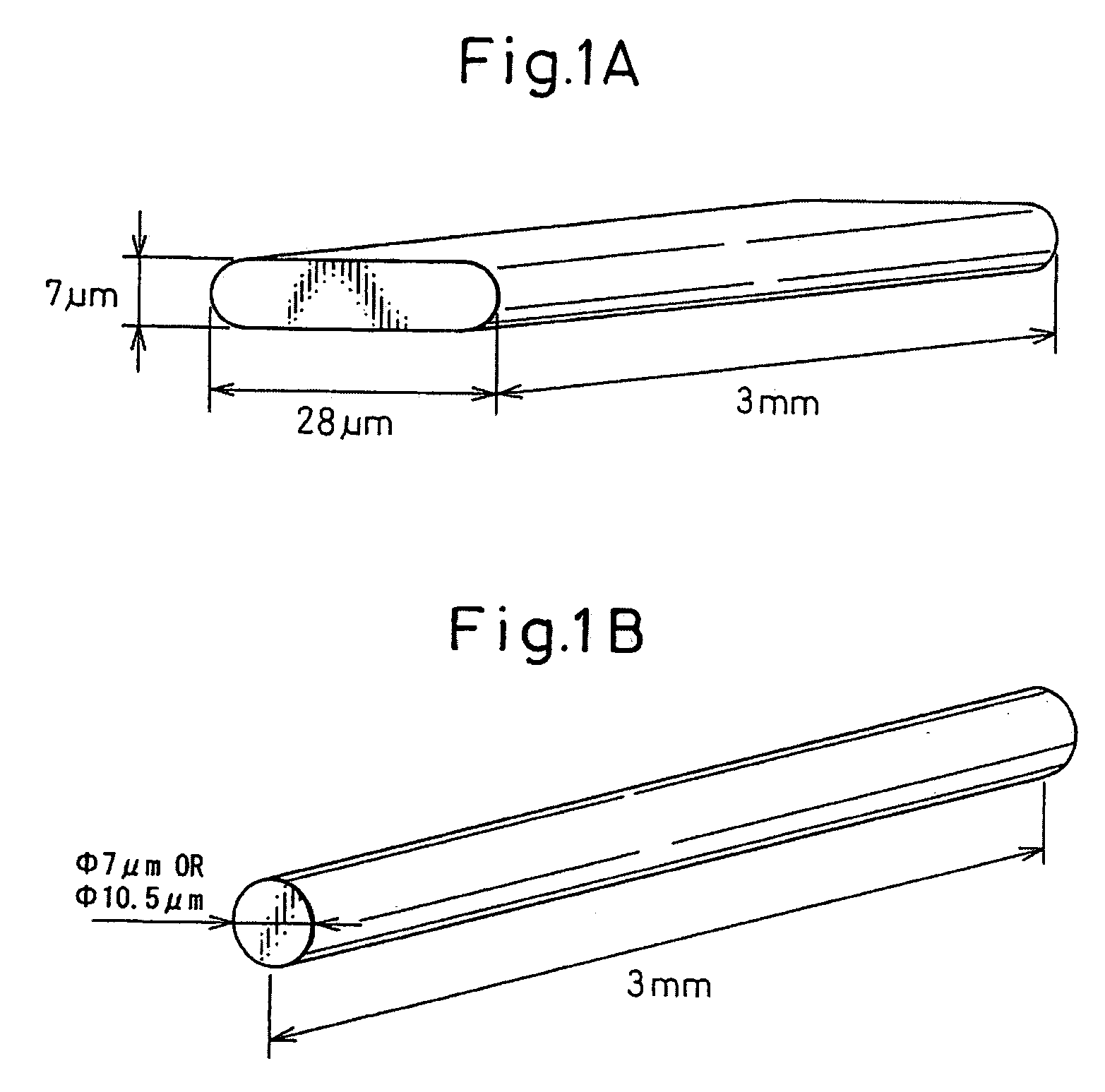
[0017]As a result of intensive studies, the present inventors have found that a polyamide resin composition having blended therein a glass fiber having a non-circular cross-section with the ratio between the long diameter and the short diameter in the cross-section at right angles to the length direction being from 1.2 to 10 is excellent in laser transmittance, as well as low warpage and when shaping parts each comprising this polyamide resin composition are laser-welded to each other, a shaped article having high weld strength and uniform weld strength can be obtained. The present invention has been accomplished based on this finding.

Problems solved by technology

However, the adhesive strength in joining with an adhesive, and the cost, labor of fastening, and increase in weight in the mechanical joining with a bolt or the like become problems.
In this laser welding method, if the energy loss of laser light transmitting through the transmissive resin material is large, heat-melting at the joining interface between the non-transmissive resin material and the transmissive resin material becomes insufficient, and satisfactory weld strength cannot be achieved.
However, the laser transmittance of a polyamide resin, for example, is greatly reduced by blending a general glass fiber having a fiber diameter of around 10 μm and there arises a problem that a sufficiently large amount of laser energy cannot arrive at and be absorbed by the abutting surface of the non-transmissive resin material.
In order to solve this problem, a technique of using laser light at a wavelength of 1.5 to 2.5 μm (see, Japanese Patent No. 3,630,293), or making the crystallinity of the joining part lower than that of other parts (see, Japanese Patent No. 3,596,456) has been proposed, but these methods are disadvantageous in that the applicable range is limited and when the amount of a glass fiber blended exceeds 30 wt %, satisfactory laser transmittance cannot be obtained.
The gap between resin members is the result of warpage deformation of each resin member, and the warpage deformation inevitably occurs in an injection-molded article of a glass fiber-reinforced resin, such as a polyamide, polyethylene, polyacetal and polyester.
However, the combination of an amorphous thermoplastic resin in a large amount is not preferred in many cases, because the innate characteristic features of a crystalline thermoplastic resin, such as chemical resistance and thermal deformation temperature, are generally impaired.
However, when blending of the ore powder as above a problem occurs in which there is a serious reduction in the laser transmittance.
According to this method, gapless welding becomes possible, but since heat-melting is performed while mechanically regulating and correcting the position between a pair of members to be engaged, in the case of a product requiring large correction, i.e., generating large warpage deformation, the strain resulting from the correction is large.
The strain may be relieved in the portion melted by laser, but in many products, the welded part does not correspond to the site subjected to generation of strain and the strain may be disadvantageously frozen.
As a result, in use of the product, for example, creep fracture, local fracture or cracking due to a heating-cooling cycle may occur.
Furthermore, since a projected part is provided in the transmission-side member, laser light must transmit through a thick projected part and this may cause a large transmission loss of the laser light and insufficient weld-bonding.
Accordingly, there is a problem that in the case where the product shape is limited, the wall thickness suitable for weld-bonding cannot be maintained.

Method used


Image

  • Material for Laser Welding
  • Material for Laser Welding
  • Material for Laser Welding

Examples


examples

[0047]The present invention is described in greater detail below by referring to Examples and Comparative Examples, but the present invention is not limited to these Examples.

[0048]The methods for measuring the physical properties of the resins and shaped articles used in Examples and Comparative Examples are described below.

(1) Tensile Strength and Tensile Failure Strain

[0049]The test was performed using a specimen of 4 mm in thickness at a tensile speed of 5 mm / min according to ISO527-1,2 at ordinary temperature (n=5) (ordinary temperature is room temperature).

(2) Tensile Modulus

[0050]The test was performed using a specimen of 4 mm in thickness at a tensile speed of 1 mm / min according to ISO527-1,2 at ordinary temperature (n=5).

(3) Charpy Impact Strength

[0051]An edgewise impact test was performed using an A-notched specimen of 4 mm in thickness according to ISO179-1 at ordinary temperature (n=10).

(4) Warpage Amount

[0052]A D1 die (60×60×1 t) of ISO294-3 was shape-formed under the f...

examples 1 to 4

[0063]A polyamide resin and a glass fiber shown in Table 1 were melt-kneaded by TEX44HCT twin-screw kneader to prepare a pellet of the objective polyamide resin composition.

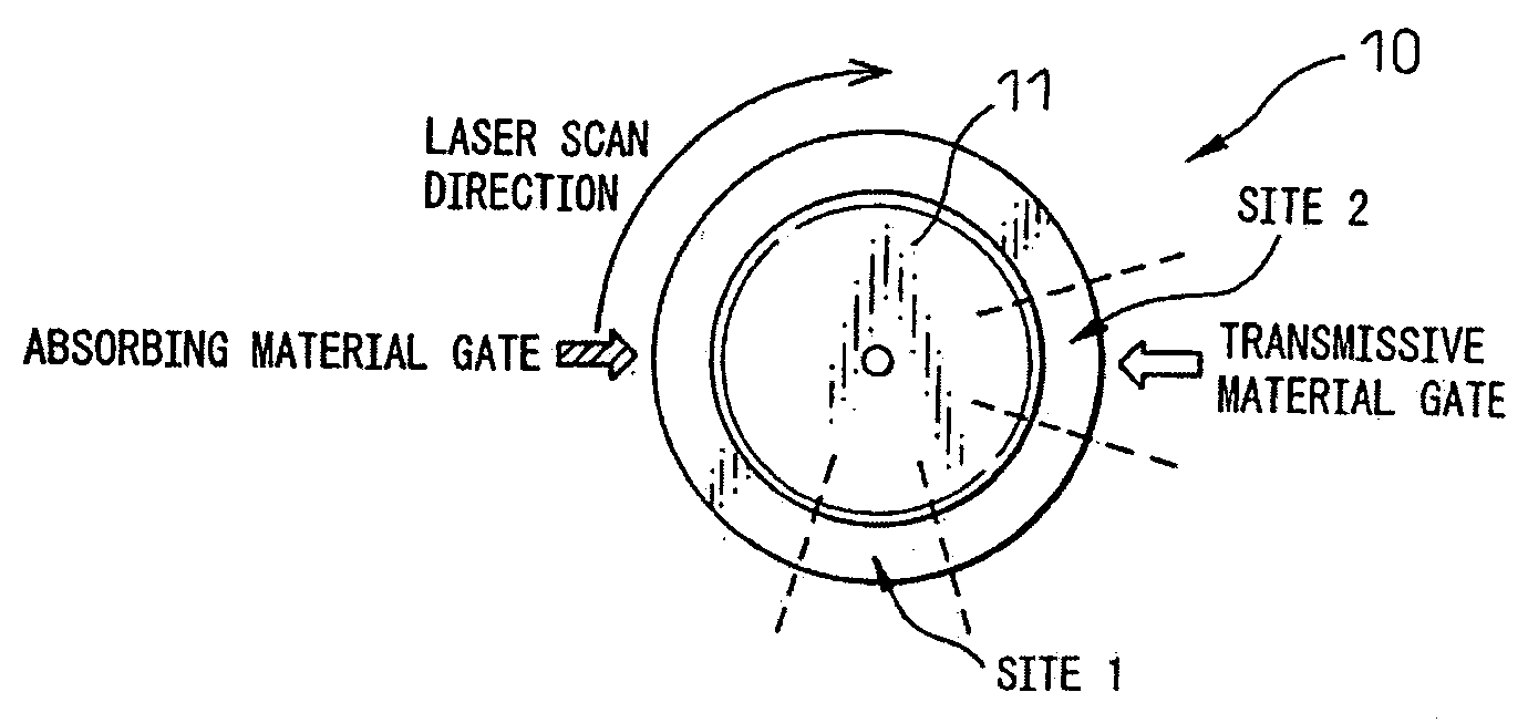
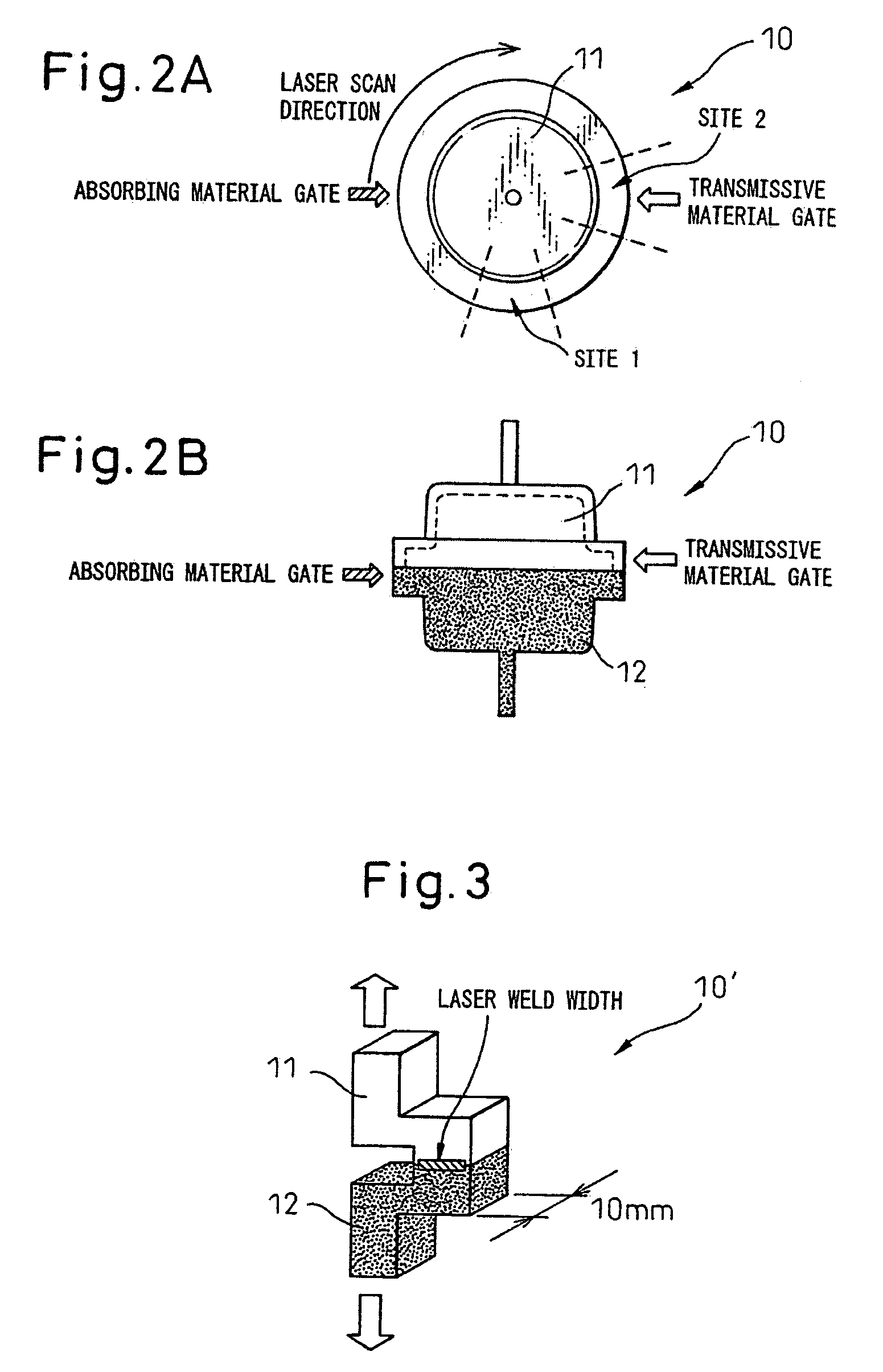
[0064]The obtained pellet was injection-molded at a cylinder temperature of 290° C. and a die temperature of 80° C. to produce various specimens. FIGS. 2A and 2B show a plan view and a side view of the test vessel 10. Sites 1 and 2 of the test vessel 10 were cut out to prepare a 10 mm-width specimen 10′ shown in FIG. 3. Accordingly, FIG. 3 shows the cross-sectional shape in the vicinity of the welded part of the test vessel 10. The laser weld strength was measured using this FIG. 3.

[0065]In addition, various physical properties, laser transmittance and warpage amount were evaluated using various specimens of polyamide resin compositions prepared. The results obtained are shown in Table 1.

[0066]The laser weld strength was also measured by the following method, and the results are shown in Table 1.

[0067]A resin com...


PUM

PropertyMeasurementUnit
Fractionaaaaaaaaaa
Fractionaaaaaaaaaa
Transmittivityaaaaaaaaaa

Abstract

To provide a material for laser welding, which is excellent in laser transmittance, as well as low warpage and enables a shaped article to be obtained with high weld strength and uniform weld strength by laser welding. This material for laser welding comprises a thermoplastic resin composition containing (A) a thermoplastic resin and (B) a glass fiber having a non-circular cross-section with the ratio between the long diameter and the short diameter in the cross-section at right angles to the length direction being from 1.2 to 10.

Description

TECHNICAL FIELD[0001]The present invention relates to a material for laser welding, which is used for welding together resin members by irradiating laser light. More specifically, the present invention relates to a material for laser welding, which is excellent in the mechanical property, low warpage and laser weldability.BACKGROUND ART[0002]In recent years, from the standpoint of reducing the weight, cost and the like, parts in various fields, such as automobile parts and electric parts, are often resinified into a resin shaped article. In view of high productivity and the like, the resin shaped article is produced in many cases by a method of shape-forming a plurality of resin members into which the resin shaped article is previously divided, and joining together the resin members.[0003]In joining the resin members, for example, joining by an adhesive agent or mechanical joining with a bolt or the like is performed. However, the adhesive strength in joining with an adhesive, and t...

Claims


Application Information

Patent Timeline
IPC IPC(8): F02M35/10C08K3/40B32B5/02B23K26/00B29C65/16B29K77/00C08K7/14C08L77/00
CPCB29C45/006B29C65/8215B29C47/0019B29C47/0023B29C49/00B29C65/1606B29C65/1616B29C65/1635B29C65/1654B29C65/1677B29C65/168B29C65/1683B29C65/5057B29C65/8207B29C66/1142B29C66/1312B29C66/54B29C66/652B29C66/71B29C66/7332B29K2023/06B29K2023/12B29K2025/00B29K2033/12B29K2055/02B29K2067/00B29K2067/006B29K2069/00B29K2077/00B29K2081/04B29K2101/12B29K2105/12B29K2309/08B29K2995/002B29K2995/0027B29L2031/3431B29L2031/749B29L2031/7492C08J5/043C08J2377/00C08K7/14C08L77/02F02M35/10321F02M35/1034F02M35/1036B29C47/00C08L77/00B29C65/00B29C66/7212B29C66/7392B29C66/73921B29C66/73772B29C66/73776B29C48/00B29C48/07B29C48/09Y10T428/24994B29K2023/04B29K2023/10B29K2025/04B29K2067/003B29K2025/08B29K2025/06
Inventor KATAYAMA, TSUTOMUMIYAMOTO, AKIOFUKUI, YASUHARUHARADA, HIDEKI
Owner UBE IND LTD
Learn More