
Adaptive Low Latency Receive Queues

a low-latency message and queue technology, applied in the field of computer system communication, can solve problems such as large clusters and breakdown of configuration types

Inactive Publication Date: 2009-03-19
IBM CORP
View PDF22 Cites 39 Cited by
  • Summary
  • Abstract
  • Description
  • Claims
  • Application Information

AI Technical Summary

Benefits of technology

[0008]The present invention provides the ability to store variable length receive messages and completion information on a single receive queue in system memory which provides an extremely efficient mechanism for system software to poll received messages and identify their source. It also provides the standard InfiniBand protection mechanisms in hardware.
[0009]An object of the present invention is to provide a computer system with receive queues implemented in host system memory whereby the message data and work completion information are provided to the system in a single transfer over the processor local bus. The completion information can comprise standard IB completion information. The primary method and structure by which the present inventive embodiment achieves low latency reception is to minimize communication back and forth between the hardware adapter and memory.
[0011]Another object of the present invention is to implement a Low Latency Receive Queue (LLRQ) for the unreliable datagram (UD) transport service. In an environment comprising thousands of nodes communicating over IB fabrics and routers, the present invention provides the benefit of scalability for these large clusters. For a reliable connected transport service each node requires a QP. That type of configuration starts to breakdown with large clusters because of the demand on memory for the number of QPs required. A single LL RQ implementation in system memory according to the present invention provides better cache coherency, less memory usage, and less resources required by receiving packets from thousands of nodes onto a single LL RQ.
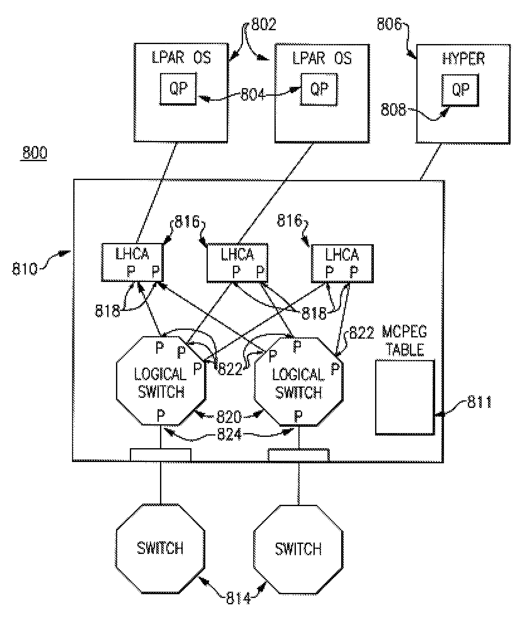
[0012]Another object of the present invention includes a data processing system and a method implemented by the data processing system whereby low latency data packets intended to be processed by the data processing system are received from a network, in particular an IB network, and examined as to their low latency status. Higher latency packets are processed in the usual manner well known to those skilled in the prior art. Low latency data packets, in particular unreliable datagram (UD) packets, take full advantage of the present embodiment of the invention. If an incoming packet is examined and determined to be a low latency unreliable datagram, then the packet is directed by front end hardware to a dedicated low latency input buffer in an adapter that is coupled to a host system and which together comprise the data processing system. The received UD packet includes a packet header containing various information fields, one of which is a queue pair (QP) number, and a payload. This QP number is used by the adapter as an index to access an entry in a QP Context table which contains further information concerning the received UD packet, for example, such as a tail pointer, free entry count, and a page table pointer. The adapter is then able to build a data message that is sent to the host system for processing in a single data transfer step that avoids typical higher latency overhead such as address translation and address fetches between the adapter and host system. The data message includes its own header, referred to as a CQE, described above, that is prepended by the adapter to the received UD packet's data payload. The CQE contains information derived from the QP Context table and also from the received UD packet header such as packet size and remote QP ID information, for example. This enables the adapter to calculate a size of the CQE+ data payload and to include size information in the QCE for use by the host system.

Problems solved by technology

That type of configuration starts to breakdown with large clusters because of the demand on memory for the number of QPs required.

Method used


Image

  • Adaptive Low Latency Receive Queues
  • Adaptive Low Latency Receive Queues
  • Adaptive Low Latency Receive Queues

Examples


Embodiment Construction

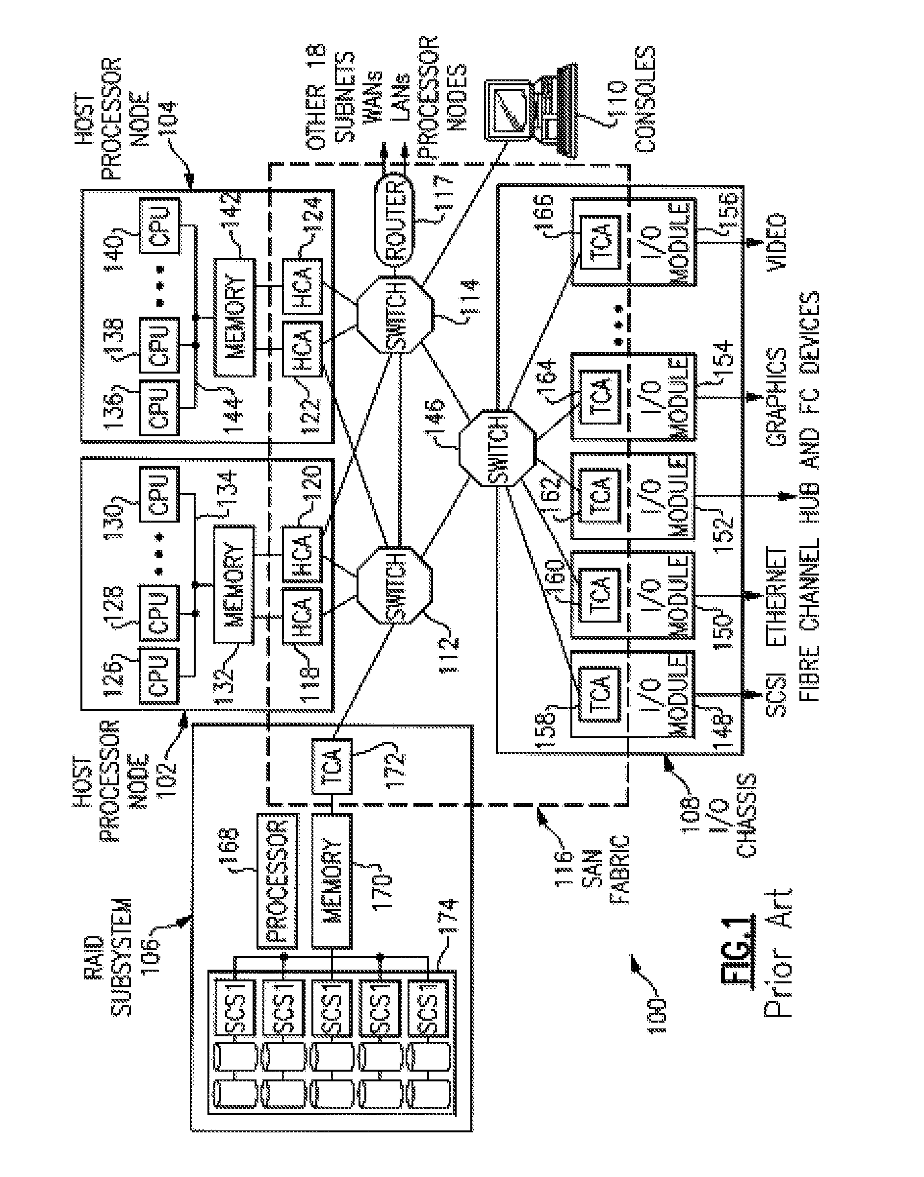
[0028]FIG. 1 is a prior art diagram of a distributed computer system where exemplary embodiments may be implemented. The distributed computer system represented in FIG. 1 takes the form of a System Area Network (SAN) 100 and is provided merely for illustrative purposes. Exemplary embodiments of the present invention described below can be implemented on computer systems of numerous other types and configurations. For example, computer systems implementing the exemplary embodiments can range from a small server with one processor and a few input / output (I / O) adapters to massively parallel supercomputer systems with hundreds or thousands of processors and thousands of I / O adapters.

[0029]Referring to FIG. 1, a SAN 100 is a high-bandwidth, low-latency network for interconnecting nodes within a distributed computer system. A node is any component attached to one or more links of a network and forming the origin and / or destination of messages within the network. In the example depicted in...


PUM


Abstract

A receive queue provided in a computer system holds work completion information and message data together. An InfiniBand hardware adapter sends a single CQE+ message data to the computer system that includes the completion Information and data. This information is sufficient for the computer system to receive and process the data message, thereby providing a highly scalable low latency receiving mechanism.

Description

CROSS REFERENCES TO RELATED APPLICATIONS [0001]U.S. patent application Ser. No. 11 / ______, IBM Docket No. POU920060247US2. entitled “Adaptive Low Latency Receive Queues”, filed Sep. 14, 2007, is assigned to the same assignee hereof, International Business Machines Corporation of Armonk, N.Y., and contains subject matter related, in certain respects, to the subject matter of the present application. The above-identified patent application is incorporated herein by reference in its entirety.BACKGROUND OF THE INVENTION [0002]1. Technical Field of the Invention[0003]This invention pertains to computer system communication. In particular, this invention provides a solution for reducing low latency message reception receive queue latency.[0004]2. Description of the Prior Art[0005]I / O adapters define queue pairs (QPs), comprising receive queues (RQ) and send queues (SQ), for conveying messaging information from a software consumer to the adapter prior to transmission over a network fabric ...

Claims


Application Information

Patent Timeline
Patent Type & Authority Applications(United States)
IPC IPC(8): G06F9/54
CPCG06F13/4022
Inventor CRADDOCK, DAVIDGREGG, THOMAS A.SCHLIPF, THOMAS
Owner IBM CORP
Learn More