
Dual wall drill string assembly

a drill string and assembly technology, applied in the direction of directional drilling, survey, borehole/well accessories, etc., can solve the problems of limiting the movement of drill pipe, affecting the formation of earth, and much, if, so as to reduce the negative environmental impact, increase the cutting volume, and the effect of large siz

Active Publication Date: 2006-11-14
U S STEEL TUBULAR PROD +1
View PDF25 Cites 50 Cited by
  • Summary
  • Abstract
  • Description
  • Claims
  • Application Information

AI Technical Summary

Benefits of technology

Enables efficient drilling in various formations with reduced environmental impact, longer borehole distances, and increased cutting capacity, while minimizing borehole damage and risk of short circuiting, facilitating more flexible and cost-effective subsurface drilling operations.

Problems solved by technology

This method of drilling is controllable, but it is dangerous.
Further, when the returned drilling mud or fluids and cuttings pass through the drilled hole, the hole can become plugged, thereby limiting the movement of the drill pipe.
This technique, however, impacts the earth's formation by forming cracks in the borehole, for example.
Typically, much, if not all of the additional mud flows into the cracks and / or produces additional cracks.
In addition, when the hole is close to the surface, the additional mud can seep or flow to the surface in a process known as “fracing out,” which raises environmental concerns.
The drill pipe typically used in reverse circulation drilling, however, is very stiff and difficult to steer and bend in a borehole.
Thus, its use is limited to relatively straight hole applications, and it is not typically used in deviated hole drilling applications, which are commonly used in the construction, oil and gas, and mining industries.
However, these wires are typically exposed and, therefore, are vulnerable to damage from short circuiting and breakage during the drilling operation.

Method used


Image

  • Dual wall drill string assembly
  • Dual wall drill string assembly
  • Dual wall drill string assembly

Examples


Embodiment Construction

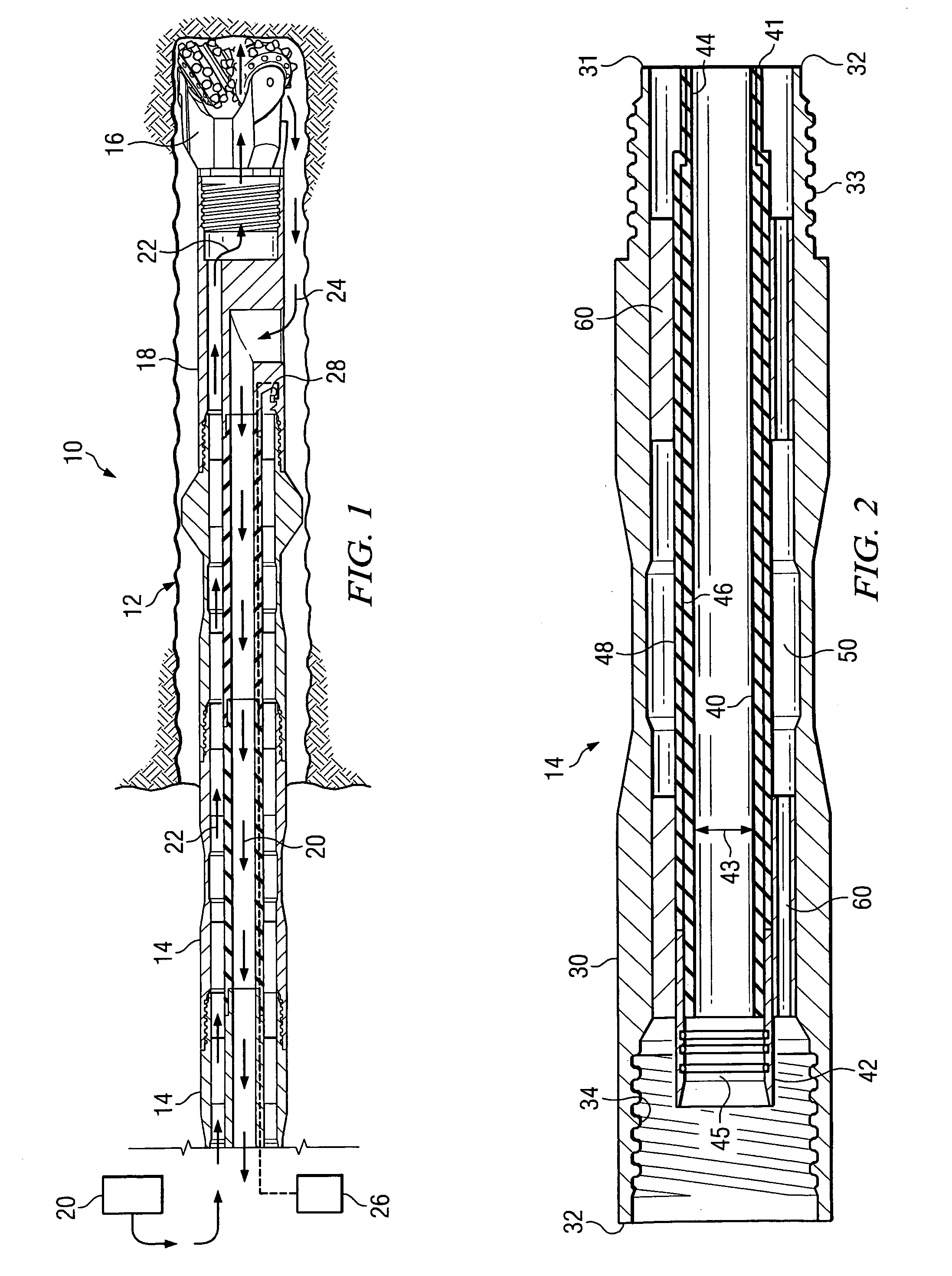
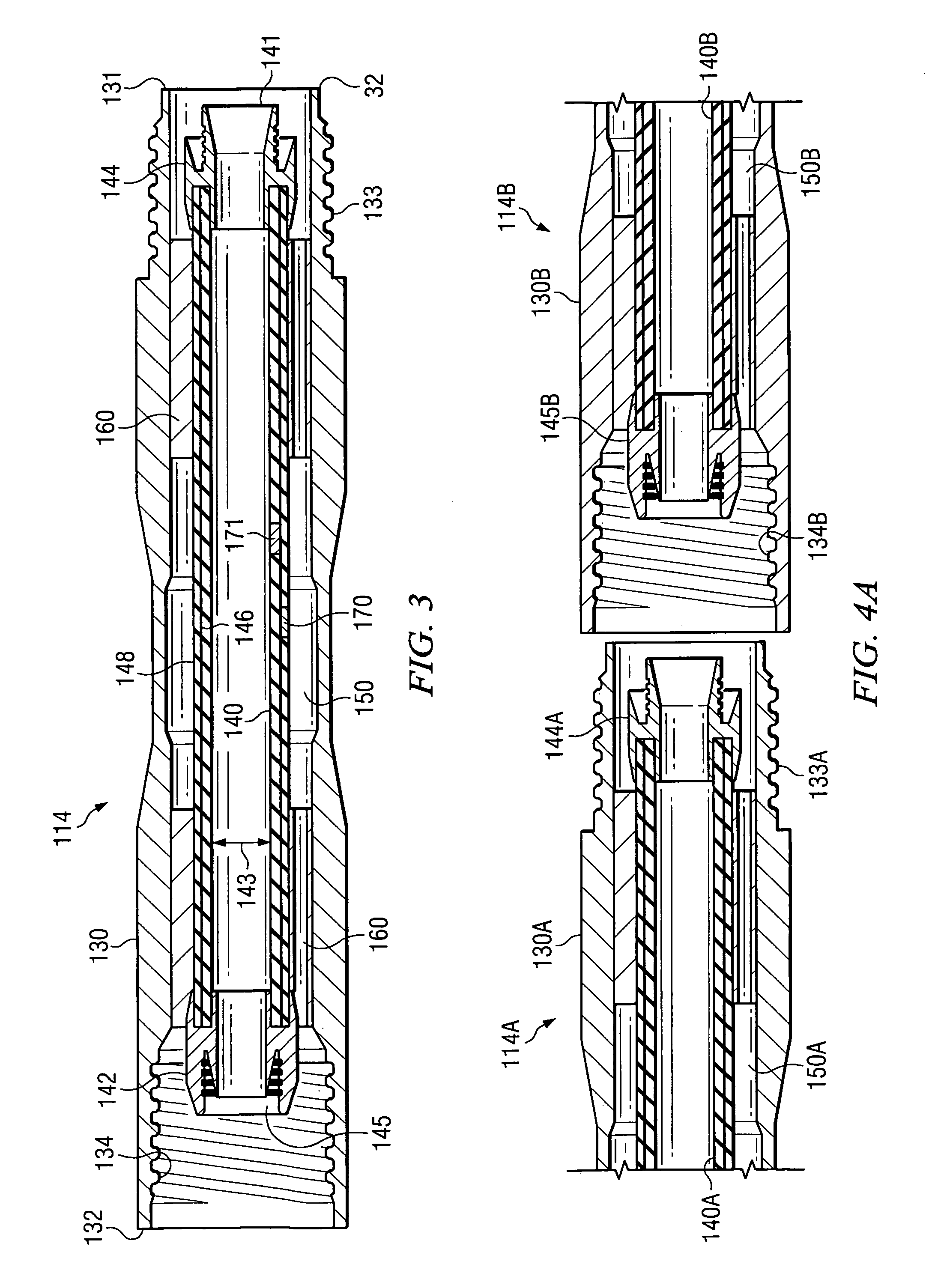
[0032]Referring now to the drawings, the apparatus of the invention claimed herein is illustrated by FIGS. 1 through 8. FIG. 1 illustrates a preferred embodiment of the dual wall drill string assembly partially in a subsurface borehole. The preferred dual wall drill string assembly is designated generally by reference numeral 10 and the subsurface borehole is designated by reference numeral 12. As shown in FIG. 1, the preferred drill string assembly may comprise a plurality of dual wall pipe sections 14. It is contemplated, however, that the drill string assembly of the invention claimed herein may comprise a single dual wall pipe. The preferred drill string assembly may further comprise a drilling mechanism, an interchange sub, a means for conveying fluid under pressure, a signal source such as a transmitter or a source of electricity, a receiver, and a navigation transmitter as described in more detail below. It is further contemplated that the assembly may be used in connection w...


PUM


Abstract

A dual wall drill string assembly for subsurface drilling. The drill string assembly includes a metallic outer tube having an outer tube first end and an outer tube second end opposite the outer tube first end. The assembly also includes a flexible, substantially non-metallic inner tube that is substantially enclosed within and generally coaxially aligned with the outer tube. The flexible, substantially non-metallic inner tube has an inner tube first end, an inner tube second end opposite the inner tube first end, and an inner tube inner diameter. The inner tube and the outer tube define an annular channel therebetween. The drill string assembly also includes a means for conveying fluid through the annular channel toward the inner tube first end. The annular channel is adapted to convey drilling fluid under pressure toward the inner tube first end, and the inner tube is adapted to convey cuttings toward the inner tube second end.

Description

FIELD OF THE INVENTION[0001]The present invention relates generally to drill string assemblies. More particularly, the invention relates to a dual wall drill string assembly for use in subsurface drilling applications.BACKGROUND AND DESCRIPTION OF THE PRIOR ART[0002]Drill pipe is used in various ways and for different applications such as mining for diamonds, installing public and private utilities, drilling for oil and gas, creating an avenue to link the surface to one or more reservoirs, and linking a location on the surface or the subsurface with another surface or subsurface location. Accordingly, drill pipe comes in specialized configurations particularly adapted for use in one or more different applications. For example, drill pipe may comprise a single wall construction made from exotic steels to withstand hostile fluid and gases. Alternatively, drill pipe may comprise a dual wall construction adapted for use in reverse circulation drilling applications. Depending upon the ap...

Claims


Application Information

Patent Timeline
Patent Type & Authority Patents(United States)
IPC IPC(8): E21B21/12E21B7/06E21B17/00E21B17/18E21B17/20E21B47/06
CPCE21B7/068E21B17/003E21B17/18E21B17/203E21B17/206E21B47/06
Inventor RIEL, BILLCHURCH, KRIS
Owner U S STEEL TUBULAR PROD
Learn More