
Method of Producing Thermoplastic Polymer Solution

a thermoplastic polymer and solution technology, applied in the direction of cleaning process and equipment, cleaning of hollow objects, chemistry apparatus and processes, etc., can solve the problems of slow dissolution rate, overly long time required for the dissolution process, and insufficient dissolution rate of methods in which solid-state polymer is dissolved

Inactive Publication Date: 2008-10-09
ASAHI KASEI CHEM CORP
View PDF4 Cites 7 Cited by
  • Summary
  • Abstract
  • Description
  • Claims
  • Application Information

AI Technical Summary

Benefits of technology

[0045]A method of producing a solution of a thermoplastic polymer and / or a solution of a depolymerization product of a thermoplastic polymer, a method of depolymerizing a polycondensation polymer, and a method of cleaning a polymerization reactor for a polycondensation polymer according to the present invention exhibit the effects described below.
(1) By distributing the thermoplastic polymer using a perforated plate, a large quantity of polymer can be treated efficiently and evenly. Because the polymer is retained on the support, the surface area of the surface layer can be increased, thereby facilitating the contact between the polymer and the solvent vapor, and ensuring a more efficient dissolution process. Furthermore, because the polymers retained on each of the support does not merge to form aggregates, no deterioration occurs in the efficiency of the treatment process.
(2) By causing the thermoplastic polymer to fall down the surface of the support under the effects of gravity, dissolved and / or depolymerized polymers, which exhibit a lower viscosity, fall more rapidly, enabling the quantity of polymer treated to be increased. Furthermore, the solution of polymers and the like dissolved first within the surface layer falls down over the surface of polymer positioned closer to the interior, which has not yet dissolved (swollen) adequately and exhibits a comparatively higher viscosity, and consequently the interior polymer is stretched by the application of a shearing force, thereby ensuring a more efficient dissolution and / or depolymerization.
(3) By contacting with a solvent vapor, a large quantity of polymer can be readily dissolved using a small quantity of solvent, enabling the production of a solution with any desired viscosity from low viscosity through to high viscosity. By using at least one component contained within the solvent vapor functions as a molecular weight reducing agent for the thermoplastic polymer, the depolymerization can be conducted more efficiently.
(4) Because the dissolution rate and / or the depolymerization rate can be increased, the dissolution time and / or depolymerization time can be reduced, deterioration in the product properties is few, and the generation of thermal degradation products and contamination caused by these thermal degradation products is also few.

Problems solved by technology

However, methods in which a solid-state polymer is dissolved tend to suffer from inadequate dissolution rates, even if the solvent is heated to improve the dissolution rate, meaning the time required for the dissolution process is overly long.
Furthermore, methods in which a melted polymer is dissolved in the solvent tend to suffer different problems, including aggregation of the melted polymer within the solvent, which results in a slower dissolution rate, and solidification and accumulation of those portions of the polymer that exhibit poor fluidity during stirring within the solvent, which causes a deterioration in the solubility.
However, as with earlier methods, the dissolution rate for this method is not particularly high, meaning the method is not particularly efficient.
The demand for used drink bottles generated is particularly significant, and the processing of these bottles poses a considerable social problem.
However, when improvers are melt kneaded into a polycondensation polymer, thermal decomposition of the polymer usually occurs, meaning a reduction in the molecular weight, and a deterioration in the polymer quality, such as the coloring and the level of accumulation of decomposition products, are unavoidable.
Methods in which the improvers are added directly to the reaction system used for producing the polycondensation polymer, thereby removing the need for a melt kneading process, are conceivable, but in most cases, the improver undergoes thermal degradation at the polymerization temperature of the polycondensation polymer, meaning the polymer quality, including the coloring and the level of accumulation of decomposition products, is actually inferior to that of the original polymer undergoing improvement.
Even in methods in which another monomer is included in the copolymerization, because the melting point and thermal decomposition temperature vary from monomer to monomer, other components with low levels of heat resistance also undergo thermal degradation under the polymerization conditions, causing the molecular weight to be reduced and the polymer quality such as the coloring and the level of accumulation of decomposition products to be inferior to that of the original polymer undergoing improvement.
In these tests in which certain properties of the polymer are improved by the copolymerization of different monomers or the blending of improvers, the quality of the product polymer is significantly inferior to that of the original polymer, meaning significant improvements in the production technology are required.
However, after polymerization has been conducted using this polymerization reactor, when the operation is halted, the inside of the polymerization reactor is prone to the retention of residual polymerization intermediates, raw materials, and modified products thereof.
However, if an attempt is made to apply this type of method to this polymerization reactor of the present invention described above, there was a problem of requiring very long time for carrying out depolymerization of the residual polymer, not only is a large quantity of residual polymer and the like retained on the support inside the polymerization reactor, but because the reactor is also not provided with a stirring device,

Method used


Image

  • Method of Producing Thermoplastic Polymer Solution
  • Method of Producing Thermoplastic Polymer Solution
  • Method of Producing Thermoplastic Polymer Solution

Examples


example 1

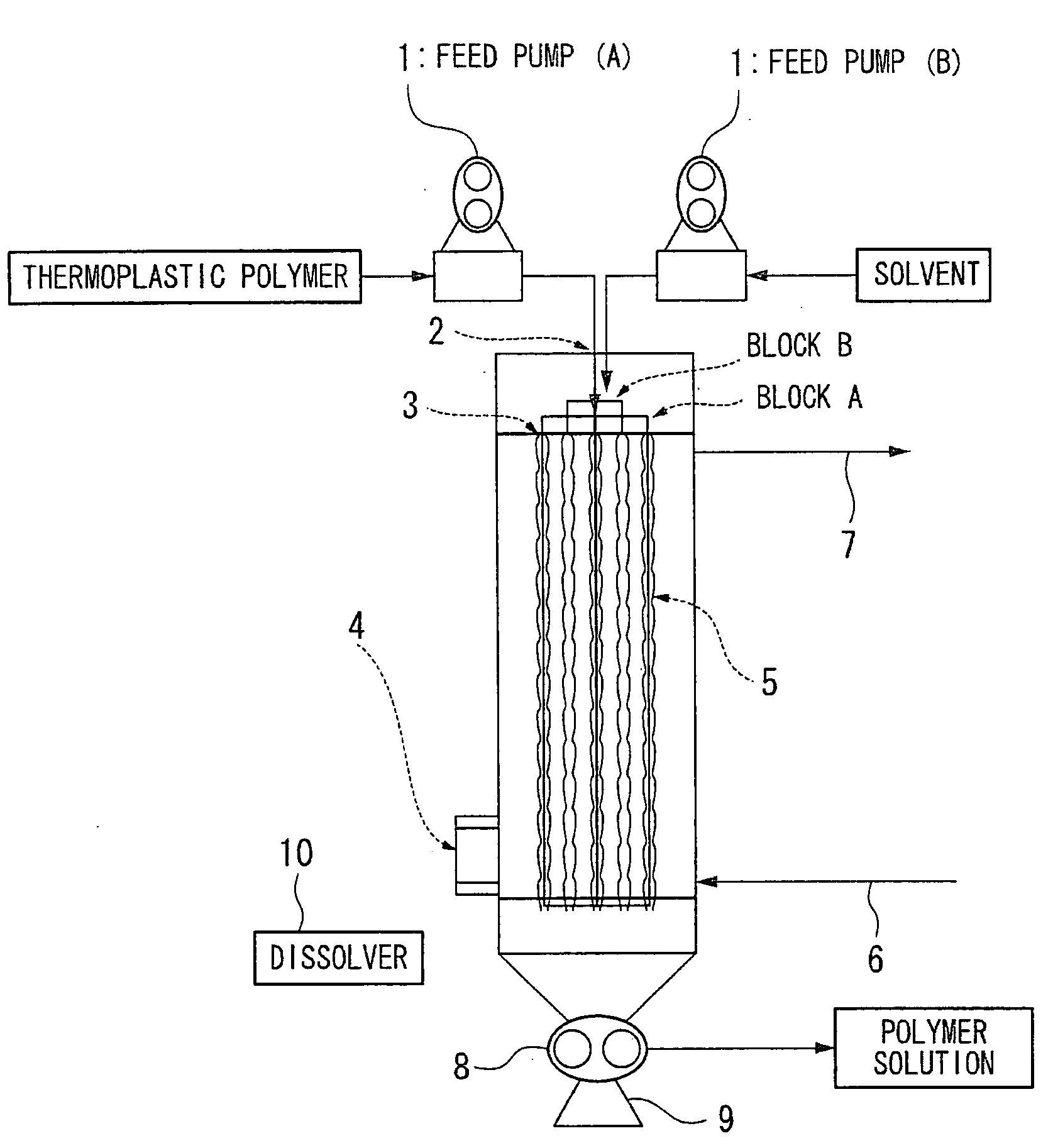
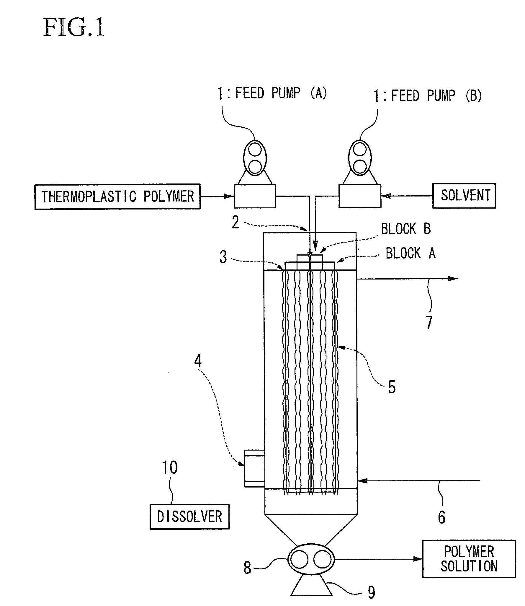
[0298]Using the reactor shown in FIG. 1, a PET resin was dissolved, yielding a PET resin solution.

[0299]The PET resin was melted a temperature of 265° C., and using the feed pump (A) 1, was then discharged from the raw material supply port 2 and through the holes of block A of the perforated plate 3 at a rate of 3.0 g / minute per hole. At the same time, isophorone was supplied as the solvent, and using the feed pump (B) 1, was discharged from the raw material supply port 2 and through the holes of block B of the perforated plate 3 at a rate of 7.0 g / minute per hole.

[0300]These supplied materials were then caused to flow down along the support at an atmospheric temperature equal to the discharge temperature, while the PET resin dissolved in the solvent, and the resulting solution was then discharged from the dissolver 10 using the drainage pump 8.

[0301]The polymer solution was allowed to accumulate at the bottom of the dissolver, and by extracting the polymer solution at a rate that m...

example 2

[0303]Using the reactor shown in FIG. 3, flakes of collected waste PET bottles were melted, and using the feed pump (A) 1, were then supplied from the raw material supply port 2 to the depolymerization reactor 10, and discharged through the holes of block A of the perforated plate 3, in a melted state at 255° C. and at a rate of 7.0 g / minute per hole. At the same time, ethylene glycol was supplied as a molecular weight reducing agent, and using the feed pump (B) 1, was supplied from the raw material supply port 2 to the depolymerization reactor 10, and discharged through the holes of block B of the perforated plate 3 at a rate of 2.3 g / minute per hole.

[0304]These supplied materials were then caused to flow down along the supports at an atmospheric temperature equal to the discharge temperature, while depolymerization was conducted at a reduced pressure of 85,000 Pa, and the resulting reaction product accumulated in the bottom of the depolymerization reactor, and was discharged from ...

example 31

[0315]Using the reactor shown in FIG. 7, a PET prepolymer with a limiting viscosity [η] of 0.46 dl / g, a carboxyl group quantity at the polymer terminals of 32 meq / kg, and a crystalline melting point of 260° C. was supplied from the raw material supply port 2 to the polymerization reactor 10 using the feed pump (A) 1, and was discharged through the holes of block A of the perforated plate 3, in a melted state at 265° C. and at a rate of 10 g / minute per hole. At the same time, a prepolymer produced by copolymerizing 4 mol % of cyclohexanedimethanol with a PET with a limiting viscosity [η] of 0.28 du / g, a carboxyl group quantity at the polymer terminals of 30 meq / kg, and a crystalline melting point of 240° C. was supplied from the raw material supply port 2 to the polymerization reactor 10 using the feed pump (B) 1, and was discharged through the holes of block B of the perforated plate 3, in a melted state at 265° C. and at a rate of 10 g / minute per hole.

[0316]These supplied materials...


PUM

PropertyMeasurementUnit
Temperatureaaaaaaaaaa
Distanceaaaaaaaaaa
Temperatureaaaaaaaaaa

Abstract

An object of the present invention is to provide a method of producing a solution of a thermoplastic polymer such as a polyester resin and / or a solution of a depolymerization product of a thermoplastic polymer by efficiently dissolving the thermoplastic polymer and / or the depolymerization product of the thermoplastic polymer. The method of producing a solution of a thermoplastic polymer and / or a solution of a depolymerization product of a thermoplastic polymer, which includes supplying a thermoplastic polymer, in a melted state, from a raw material supply port to an interior of a reactor, discharging the polymer through holes of a perforated plate, and then bringing the polymer into contact with a solvent vapor while flowing down along the surface of a support disposed inside the reactor.

Description

TECHNICAL FIELD[0001]The present invention relates to a method of producing a solution of a thermoplastic polymer and / or a solution of a depolymerization product of a thermoplastic polymer providing a raw material for paints, polymer powders and the like. Furthermore, the present invention also relates to a method of cleaning any polymer, polymerization intermediate, or modified products thereof left within a melt polymerization reactor that is used for producing a polycondensation polymer by supplying a polymerization intermediate, in a melted state, from a raw material supply port to the interior of the melt polymerization reactor, and the intermediate is then discharged through the holes of polymerization intermediate through the holes of a perforated plate, and then producing the polycondensation polymer while the polymerization intermediate flows down the surface of the support disposed inside the reactor.[0002]The present application is claimed priority to the Japanese patent ...

Claims


Application Information

Patent Timeline
IPC IPC(8): C08G63/88C08G69/46C08G85/00B08B5/00
CPCC08G63/88C08G85/008C08J3/095C08G85/00
Inventor YOKOYAMA, HIROSHIAMINAKA, MUNEAKI
Owner ASAHI KASEI CHEM CORP
Learn More