Electrode for electrolysis, electrolytic process using the electrode, and electrolytic apparatus using them
a technology of electrolysis and electrodes, applied in silicon electrodes, electrolysis coatings, manufacturing tools, etc., can solve the problems of ozone and hydrogen peroxide dissolved in aqueous solution that cannot be obtained by a single electrolysis operation, the cost of the apparatus itself, and the inability to achieve a single electrolytic operation. to achieve the effect of facilitating the production of at least on
- Summary
- Abstract
- Description
- Claims
- Application Information
AI Technical Summary
Benefits of technology
Problems solved by technology
Method used
Image
Examples
example 1
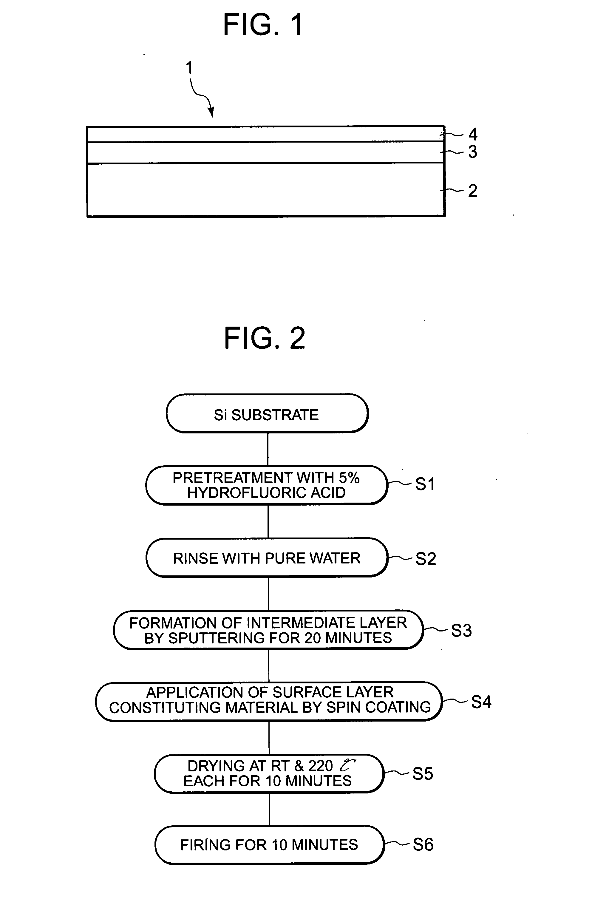
[0038]FIG. 1 is a cross-sectional plan view of an electrode 1 for electrolysis of Example 1 as one example of the electrode for electrolysis according to the present invention. The electrode 1 for electrolysis has, as shown in FIG. 1, a substrate 2, an intermediate layer 3 formed on the surface of the substrate 2, and a surface layer 4 formed on the surface of the intermediate layer 3.
[0039] In the present invention, the substrate 2 is made of a conductive material such as platinum (Pt), a valve metal such as titanium (Ti), tantalum (Ta), zirconium (Zr) or niobium (Nb), an alloy of two or more of these valve metals, or silicon. In particular, silicon having a planarized surface is employed for the substrate 2 to be used in the present Example.
[0040] The intermediate layer 3 is made of a metal resistant to oxidation such as platinum, gold (Au), a metal oxide having conductivity such as iridium oxide, palladium oxide or ruthenium oxide, or an oxide superconductor, or a metal having ...
example 2
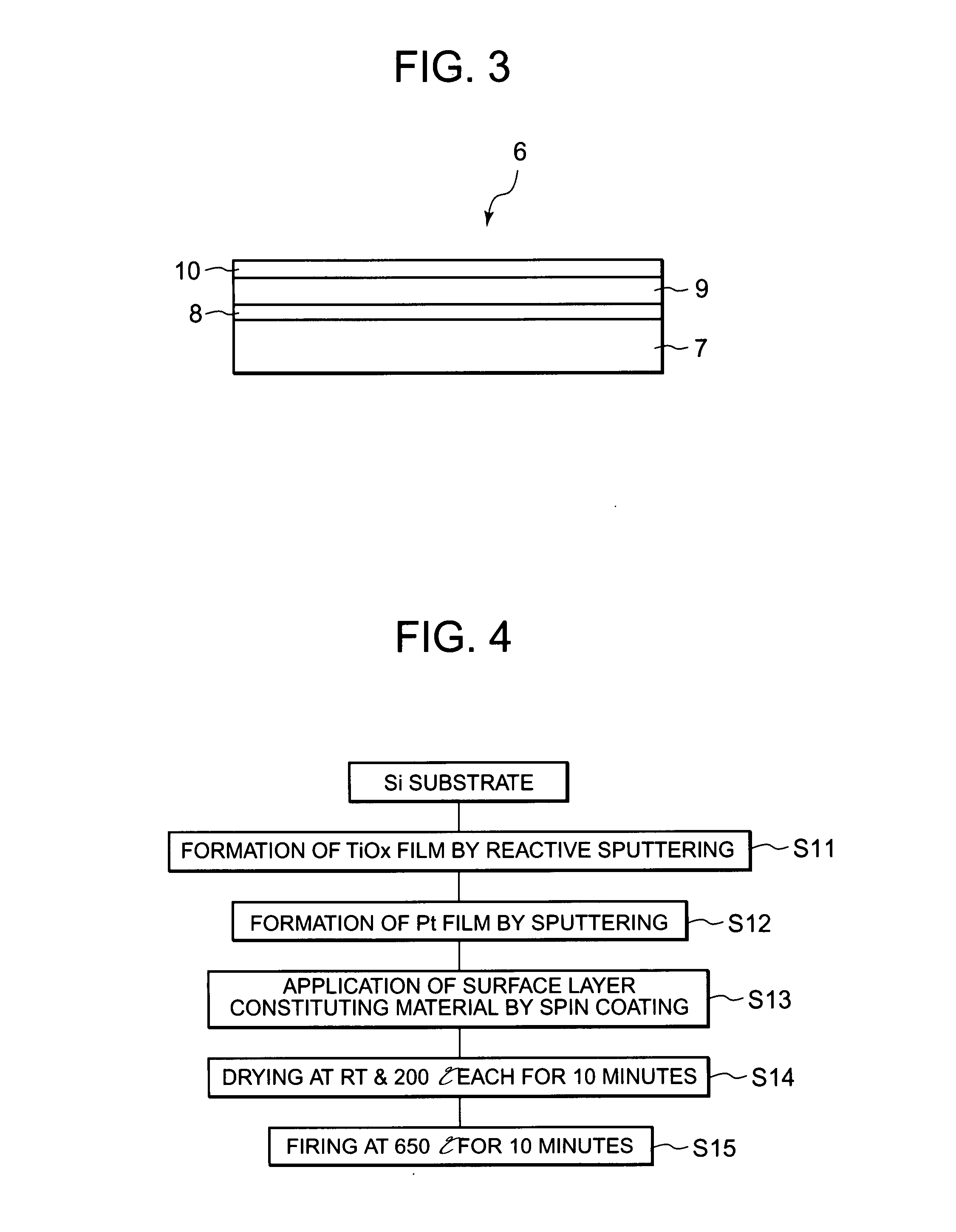
[0051] Referring to FIG. 3, a description will next be made of an electrode 6 for electrolysis according to Example 2. FIG. 3 is a cross-sectional plan view of the electrode 6 for electrolysis as one example of the electrode for electrolysis according to the present invention. As illustrated in FIG. 3, the electrode 6 for electrolysis is composed of a substrate 7, an adhesion layer 8 formed on the surface of the substrate 7, an intermediate layer 9 formed on the surface of the adhesion layer 8, and a surface layer 10 formed on the surface of the intermediate layer 9.
[0052] The substrate 7 in the present invention is made of a material similar to that constituting the substrate 2 used for the electrode 1 for electrolysis in Example 1 so that the substrate 7 in Example 2 is made of silicon.
[0053] The adhesion layer 8 is formed on the surface of the substrate 7 and serves to improve the adhesion between the substrate 7 and the intermediate layer 9 formed of, for example, platinum on ...
example 3
[0076] Electrode 26 for electrolysis in Example 3 will next be described with reference to FIG. 11. FIG. 11 is a cross-sectional plan view of the electrode 26 for electrolysis as one example of the electrode for electrolysis according to the present invention. As illustrated in FIG. 11, the electrode 26 for electrolysis has a substrate 27, an adhesion layer 28 formed on the surface of the substrate 27, an intermediate layer 29 formed on the surface of the adhesion layer 28, and a surface layer 30 formed on the surface of the intermediate layer 29. This electrode 26 for electrolysis is equipped, on the side of the substrate 27, with a titanium plate 31 as an electroconducting portion. The titanium plate 31 and the intermediate layer 29 are made conductive via a silver paste 32 serving as a conductive material disposed on the end face of the electrode 26. The silver paste 32 and titanium plate 31 are covered with a sealing material 33 and do not contribute to electrolysis.
[0077] In t...
PUM
| Property | Measurement | Unit |
|---|---|---|
| thickness | aaaaa | aaaaa |
| thickness | aaaaa | aaaaa |
| current density | aaaaa | aaaaa |
Abstract
Description
Claims
Application Information
 - R&D
- Intellectual Property
- Life Sciences
- Materials
- Tech Scout
- Unparalleled Data Quality
- Higher Quality Content
- 60% Fewer Hallucinations
Browse by: Latest US Patents, China's latest patents, Technical Efficacy Thesaurus, Application Domain, Technology Topic, Popular Technical Reports.
© 2025 PatSnap. All rights reserved.Legal|Privacy policy|Modern Slavery Act Transparency Statement|Sitemap|About US| Contact US: help@patsnap.com


