Heat riser

Inactive Publication Date: 2006-04-06
GRAFTECH INT HLDG INC
View PDF35 Cites 17 Cited by
  • Summary
  • Abstract
  • Description
  • Claims
  • Application Information

AI Technical Summary

Benefits of technology

[0015] The present invention provides a graphite-based heat riser formed from compressed particles of exfoliated graphite. More specifically, the inventive heat riser is formed of articles of epoxy impregnated graphite compressed (such as by calendering) and then cured at elevated temperatures and pressures. The resultant material exhibits unexpectedly good mechanical and thermal properties and also possesses good machinability. The thermal properties exhibited by the graphite article permit efficient transfer of heat from a heat source to a heat dissipation device such as a heat sink. Because of the efficiency of this thermal transfer, heat generated by the heat source is dissipated to a greater extent that previously anticipated.
[0017] By forming a heat riser of flexible graphite, a heat riser article can be provided to effectively bridge the gap between a heat source and a thermal dissipation device. In addition, the inventive heat riser can be shaped to fit in the required shape, and provide a direct heat transfer path to enable optimal heat transfer.
[0018] The inventive heat riser comprises two operative surfaces, one of which is arrayed in operative contact with a heat source, such as a hard drive or electronics chip in an electronic device. Indeed, the heat riser can be placed in direct contact with the heat source; alternatively, a thermal interface or like material can be disposed between the heat riser and the heat source. The second operative surface of the inventive heat riser is placed in operative contact with a heat dissipation device like the base of a heat sink. Direct contact between the heat riser and a heat sink, or with a thermal interface therebetween, can be maintained.
[0020] The inventive heat riser is shaped to optimize thermal transfer between the heat source and the heat dissipation device, although the most common shape is as a rectangular block, with the operative surfaces comprising two opposing surfaces of the heat riser. Generally, contact between the heat riser and the heat source and / or the heat dissipation device is maintained by pressure exerted on the respective devices by clamps or other holding devices. Adhesives are undesirable since they may degrade thermal transfer, although at times adhesives can be employed if they are thermally conductive or applied as a thin enough layer to reduce the amount of thermal degradation in the transfer of heat between the heat riser and heat source and between the heat riser and heat sink.
[0021] Accordingly, it is an object of the present invention to provide a heat riser for facilitating the transfer of heat from a component of an electronic device to a heat dissipation device.
[0022] Still another object of the present invention is the provision of a heat riser having a sufficiently high thermal anisotropic ratio to function effectively for optimized heat transfer from a heat source to a heat dissipation article or material.

Problems solved by technology

However, microprocessors, integrated circuits and other sophisticated electronic components typically operate efficiently only under a certain range of threshold temperatures.
The excessive heat generated during operation of these components can not only harm their own performance, but can also degrade the performance and reliability of the overall system and can even cause system failure.
The increasingly wide range of environmental conditions, including temperature extremes, in which electronic systems are expected to operate, exacerbates the negative effects of excessive heat.
However, one issue which has arisen in efficient heat dissipation from electronic devices is the space requirements and limitations in some electronics, especially portable devices like laptop computers, personal digital assistants (PDAs), cell phones and the like.
In these devices, it is often not feasible to place a heat sink or other heat dissipation device in direct operative contact with a heat source.
Although conventional gap fillers and the like can be used in some instances, the gap between the heat source and dissipation device can often be too large for gap fillers commonly used.
Likewise, the gap in these instances can be too small for use of a conventional heat transfer device like a heat pipe, which in addition would generally not have sufficient contact surface to bridge a gap between a heat source and a heat sink (and is likely cost prohibitive for this use in any event).
Accordingly, there is a continuing need for a heat riser, which will function to bridge a gap between a heat source and a heat dissipation device, where conventional gap fillers and the like will not be effective.

Method used


Image

  • Heat riser
  • Heat riser
  • Heat riser

Examples


Embodiment Construction

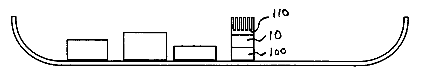
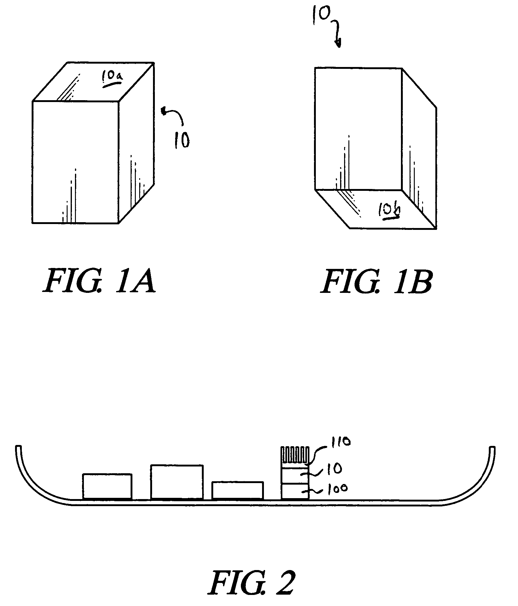
[0031] As noted, the inventive heat riser is formed from compressed particles of exfoliated graphite, commonly known as flexible graphite. Graphite is a crystalline form of carbon comprising atoms covalently bonded in flat layered planes with weaker bonds between the planes. By treating particles of graphite, such as natural graphite flake, with an intercalant of, e.g. a solution of sulfuric and nitric acid, the crystal structure of the graphite reacts to form a compound of graphite and the intercalant. The treated particles of graphite are hereafter referred to as “particles of intercalated graphite.” Upon exposure to high temperature, the intercalant within the graphite decomposes and volatilizes, causing the particles of intercalated graphite to expand in dimension as much as about 80 or more times its original volume in an accordion-like fashion in the “c” direction, i.e. in the direction perpendicular to the crystalline planes of the graphite. The exfoliated graphite particles ...


PUM


Abstract

A heat riser for bridging the gap between a heat source and a heat dissipation device in an electronic component, the heat riser formed of a flexible graphite article having two operative surfaces, one of which is in operative contact with a surface of the heat source and the other of which is in operative contact with a surface of the heat dissipation device.

Description

[0001] Be it known that we, Joseph P. Capp, a citizen of the United States of America residing at 10094 Juniper Court, Strongsville, Ohio; and Gary G. Chen, a citizen of the United States of America, residing at 5293 Big Creek Parkway, Apt. #3, Parma, Ohio, have invented a new and useful invention entitled “HEAT RISER.”TECHNICAL FIELD [0002] The present invention relates to a heat riser for bridging the gap between the heat source in an electronic device and a heat dissipation apparatus. More particularly, the inventive heat riser comprises a resin-impregnated graphite artifact formed of compressed particles of exfoliated graphite. BACKGROUND OF THE INVENTION [0003] With the development of more and more sophisticated electronic devices, including those capable of increasing processing speeds and higher frequencies, having smaller size and more complicated power requirements, and exhibiting other technological advances, such as microprocessors and integrated circuits in electronic an...

Claims


Application Information

Patent Timeline
IPC IPC(8): F28F7/00
CPCH01L23/373H01L2924/09701H05K7/20418H01L2924/0002H01L2924/00F28F7/00
Inventor CAPP, JOSEPH P.CHEN, GARY G.
Owner GRAFTECH INT HLDG INC
Why Eureka
Try Eureka