Method of fabricating n-type semiconductor diamond, and semiconductor diamond
a technology of semiconductor diamond and n-type, which is applied in the direction of crystal growth process, polycrystalline material growth, chemically reactive gas growth, etc., can solve the problems of preventing the obtaining of desired device properties, insufficient method, and insufficient large-area film or crystallinity growth, etc., to achieve high doping efficiency, high quality, and high carrier density
- Summary
- Abstract
- Description
- Claims
- Application Information
AI Technical Summary
Benefits of technology
Problems solved by technology
Method used
Image
Examples
example 1
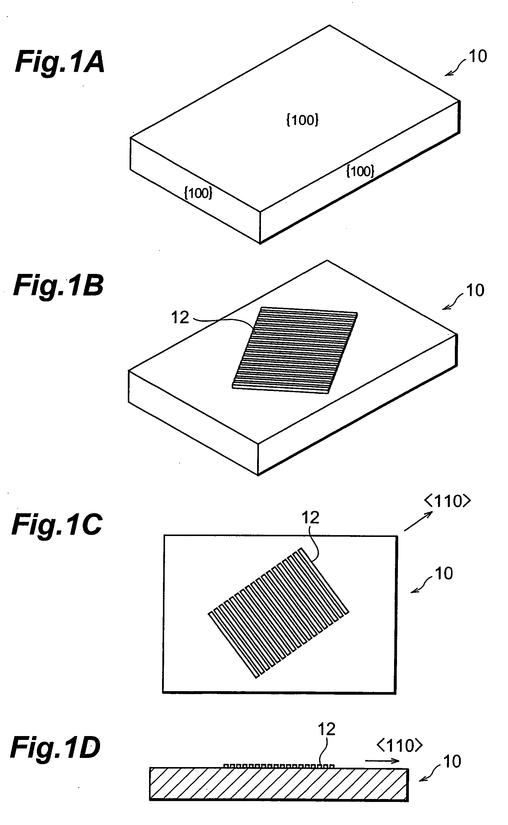
[0104] There was prepared a single crystal {100} diamond substrate which was cut such that the orientations of the top surface and side faces are {100} as shown in FIG. 1A. As shown in FIG. 1B, there was formed by a photo-lithography method, in the direction on a part of the surface of the single-crystalline {100} diamond substrate, an Al thin film mask 12 (film thickness of 0.5 μm) having a line and space pattern with the line width of 5 μm and the pitch of 5 μm.
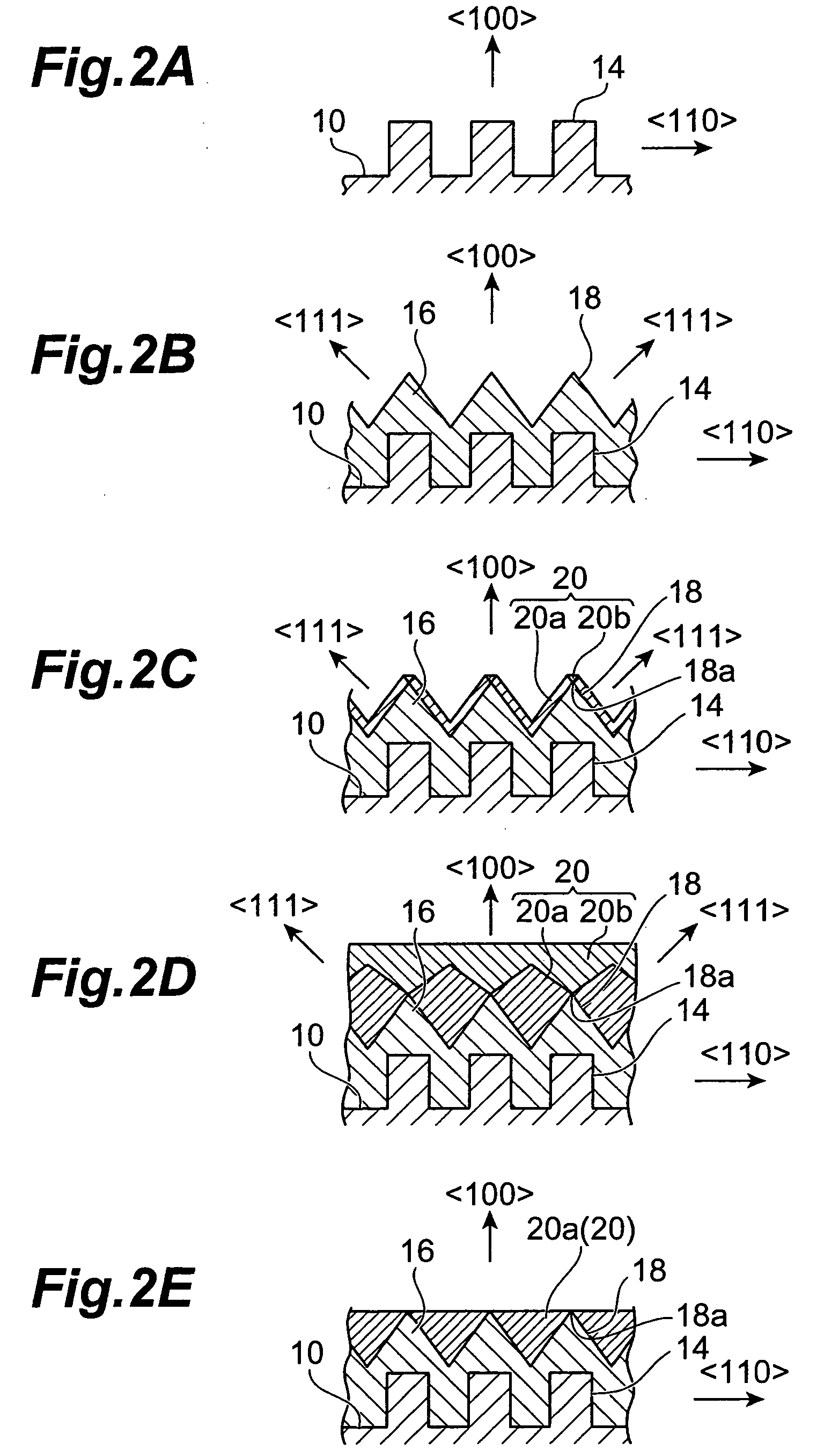
[0105] Next, The single-crystalline {100} diamond substrate patterned with the Al thin film mask 12 was transferred to dry etching device, and subjected to reactive ion etching under the conditions as follows: 99% O2 and 1% CF4 as etching gas; 200 W RF power; pressure of 6.6 Pa; 40 minutes of etching time; and 7 μm of etching depth. After that, Al thin film mask 12 was removed by means of Semico Clean. This causes, as shown in FIG. 2A, the diamond rectangular protrusion 14, rectangular in shape of a cross section and exte...
example 2
[0115] As is the case with the first example, there was prepared a single-crystalline {100} diamond substrate 10 which was cut such that the orientations of the upper face and side faces were {100}. Next, as shown in FIG. 3B, by means of photolithography, on the surface of the single-crystalline {100} diamond substrate 10 there were formed in a matrix form a plurality of circular Al thin film masks 12 with a 5 μm diameter and a 10 μm center distance.
[0116] Next, the single-crystalline {100} diamond substrate 10 patterned with the Al thin film mask 12 was transferred to dry etching device, and was subjected to restrictive ion etching under the condition similar to that of the first example. After that, Al thin mask 12 was removed using Semico Clean. This caused, as shown in FIG. 3C, a plurality of cylindrical protrusions 22 made of cylindrical diamond, arrayed side-by-side in a matrix form, to be formed on the single-crystalline {100} diamond substrate 10.
[0117] Then, using microwa...
example 3
[0125] As is the case with the first example, photolithography and reactive ion etching were applied to the single-crystalline {100} diamond substrate 10. This allowed the rectangular protrusion 14 extending in one direction of to be formed on the surface layer of the single-crystalline {100} diamond substrate 10. In FIG. 13A there is shown this rectangular protrusion 14 in a cross section taken along the plane perpendicular to the extension direction thereof. The cross section of this rectangular protrusion 14 is of the size of 5 μm width and 7 μm height. Further, the distance between adjacent rectangular protrusions 14 is 5 μm.
[0126] Next, using microwave plasma CVD device, the non-doped diamond layer 16 was formed on the rectangular protrusion 14. On this occasion the synthesis condition for the non-doped diamond is set as follows: hydrogen gas flow rate of 0.11 / min (100 sccm); methane gas flow rate of 5×10⁻³ l / min (5 sccm); pressure of 1.3×10⁴ Pa; microwave power of 300 W; sub...
PUM
| Property | Measurement | Unit |
|---|---|---|
| angle | aaaaa | aaaaa |
| band gap | aaaaa | aaaaa |
| distance | aaaaa | aaaaa |
Abstract
Description
Claims
Application Information
 - R&D
- Intellectual Property
- Life Sciences
- Materials
- Tech Scout
- Unparalleled Data Quality
- Higher Quality Content
- 60% Fewer Hallucinations
Browse by: Latest US Patents, China's latest patents, Technical Efficacy Thesaurus, Application Domain, Technology Topic, Popular Technical Reports.
© 2025 PatSnap. All rights reserved.Legal|Privacy policy|Modern Slavery Act Transparency Statement|Sitemap|About US| Contact US: help@patsnap.com


