
Microwave dielectric ceramic composition of the formula xMO-yLa2O3-zTiO2 (M= Sr, Ca; x:y:z = 1:2:4, 2:2:5, 1:2:5 or 1:4:9), method of manufacture thereof and devices comprising the same

a technology of dielectric ceramics and micro-waves, applied in the direction of waveguide devices, fixed capacitor details, fixed capacitors, etc., can solve problems such as unsuitable practical applications, and achieve the effect of avoiding any surface irregularities and maximizing microwave dielectric properties

Inactive Publication Date: 2003-09-25
COUNCIL OF SCI & IND RES
View PDF3 Cites 28 Cited by
  • Summary
  • Abstract
  • Description
  • Claims
  • Application Information

AI Technical Summary

Benefits of technology

[0027] The principal resonant mode is TE.sub.01.delta. mode. In order to minimise the effect of spurious modes on the principal mode usually a D / L ratio of 2-2.5 is good where D is the diameter and L the length of the cylindrical resonator. For narrow band width DR filters extremely high quality factor dielectric resonators are needed. The actual Q of the DR is obtained by subtracting the coupler losses. The losses due to the mounting fixture and the surrounding evanescent mode wave guide reduce the Q factor of the actual filter. The actual filter circuits employ more than one dielectric resonator, such that as the number of resonators increases, the skirt of the filters frequency response becomes steeper and out of band rejection increases. The quality factor of the resonant structure is measured to be 7100 at 4.764 GHz. The measurement set up works like a band rejection filter circuit and therefore provides an idea as to the performance of the dielectric resonator in actual working environment. The resonant curve and the corresponding Smith chart are given in FIG. 6.

Problems solved by technology

The cation deficient provskites reported such as Ba.sub.5Nb.sub.4O.sub.15 and Ba.sub.5-xSr.sub.xNb.sub.4O.sub.15, are having dielectric constant between 40 and 50 and high quality factor, but their high .tau..sub.f make them not suitable for practical applications.

Method used


Image

  • Microwave dielectric ceramic composition of the formula xMO-yLa2O3-zTiO2 (M= Sr, Ca; x:y:z = 1:2:4, 2:2:5, 1:2:5 or 1:4:9), method of manufacture thereof and devices comprising the same
  • Microwave dielectric ceramic composition of the formula xMO-yLa2O3-zTiO2 (M= Sr, Ca; x:y:z = 1:2:4, 2:2:5, 1:2:5 or 1:4:9), method of manufacture thereof and devices comprising the same
  • Microwave dielectric ceramic composition of the formula xMO-yLa2O3-zTiO2 (M= Sr, Ca; x:y:z = 1:2:4, 2:2:5, 1:2:5 or 1:4:9), method of manufacture thereof and devices comprising the same

Examples


example 3

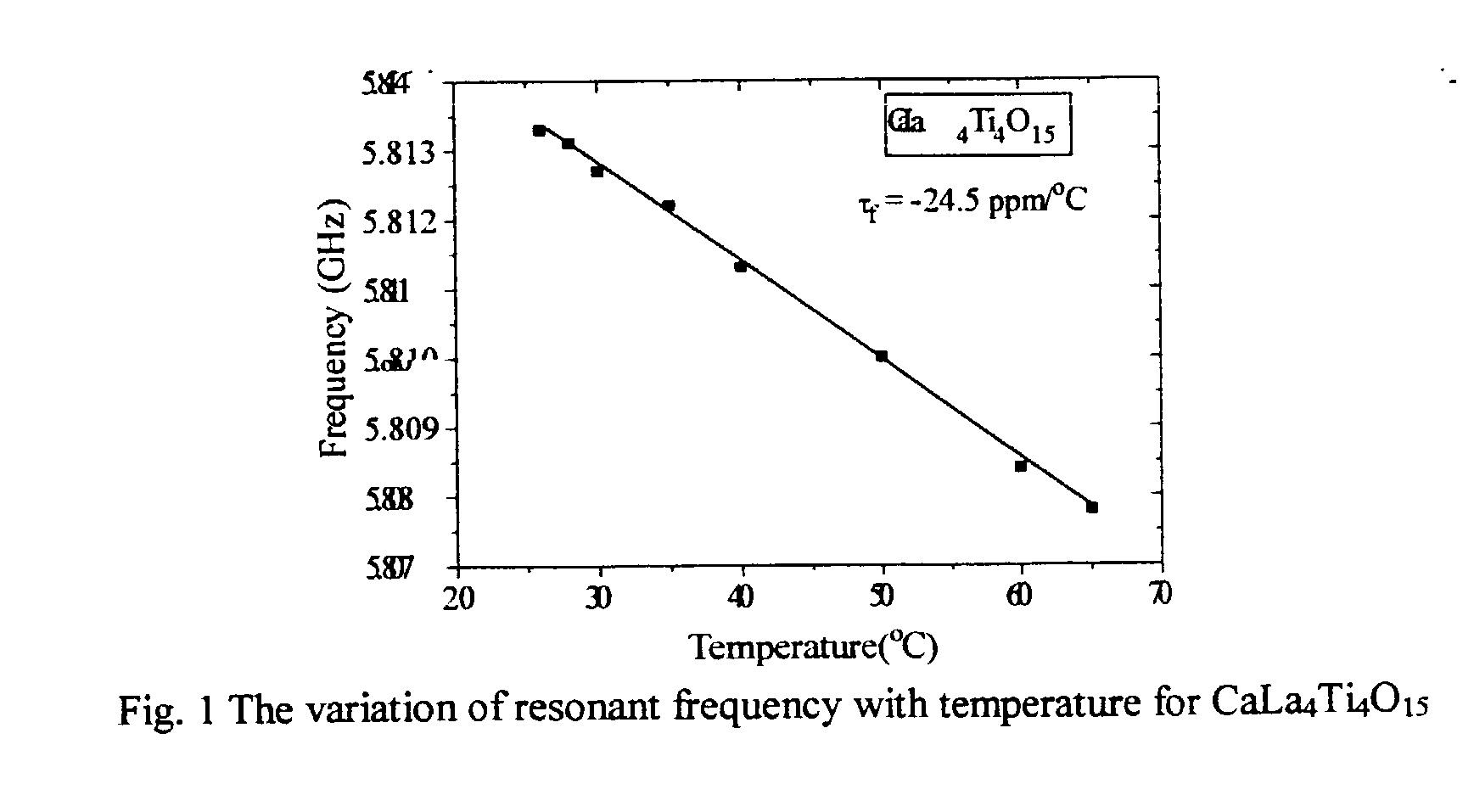
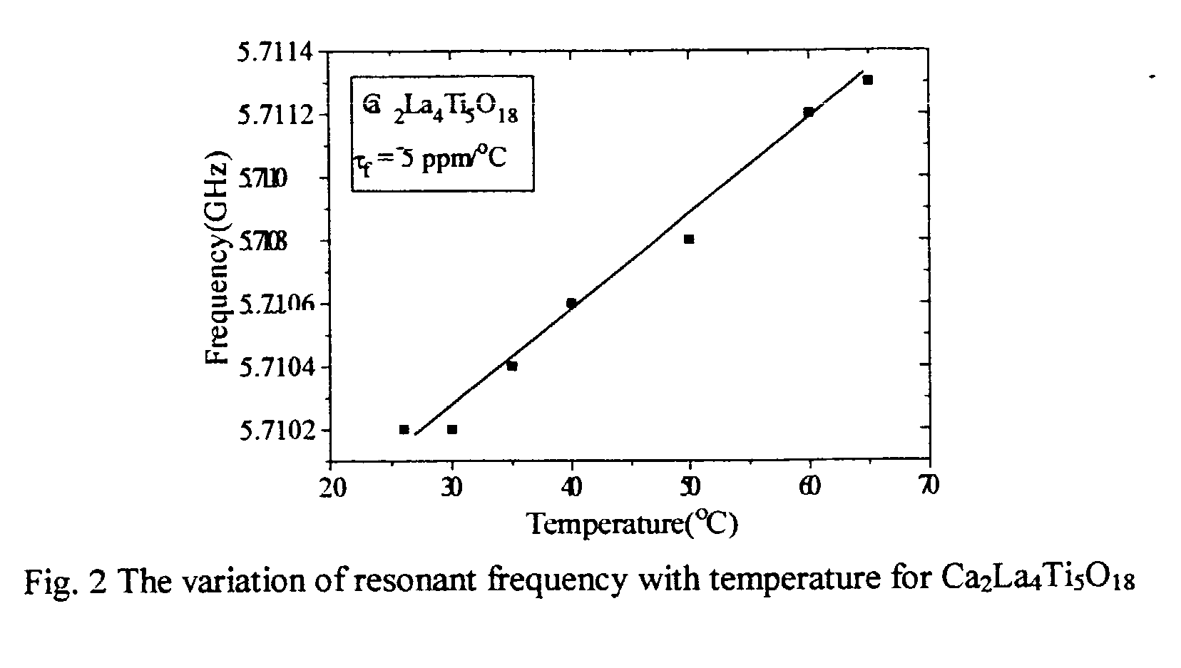
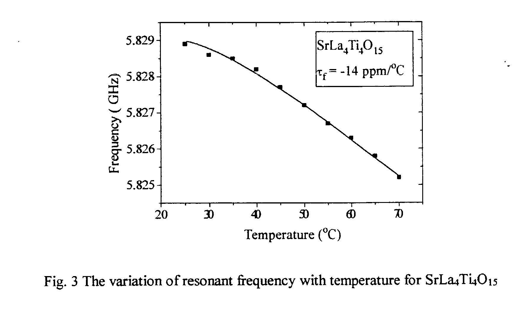
[0025] The CaO--La.sub.2O.sub.3--TiO.sub.2 ceramics including the single phase polycrystalline CaLa.sub.4Ti.sub.5O.sub.17 and CaLa.sub.8Ti.sub.9O.sub.31 are prepared by reacting high purity CaCO.sub.3, La.sub.2O.sub.3, TiO.sub.2 in the molar ratios 1:2:5 and 1:4:9 respectively through the solid state ceramic route. The preparation and characterization follows the steps given in the example-1. The firing involves initial calcination at 1200.degree. C. for 4 h, grinding well and again calcining at 1350-1450.degree. C. for different durations, optimizing sintering in the range 1600 to 1675.degree. C. for 2-8 hours. The highly dense single-phase ceramics (>93% of theoretical density) are used for microwave measurements.

3TABLE 3 The microwave dielectric properties of CaLa.sub.4Ti.sub.5O.sub.17 and CaLa.sub.8Ti.sub.9O.sub.31 Sam .tau..sub.f f Material ple .epsilon..sub.r .epsilon..sub.r(corr) ppm / .degree. C. Q GHz CaLa.sub.4Ti.sub.5O.sub.17 A 53.75 54.4 -18 7094 .+-. 300 3.6741 " B 54.11 ...

example 4

[0026] In order to study the performance of the dielectric resonator in actual working environments such as a filter, one dielectric resonator sample of CaLa4Ti4O15 was placed on PTFE substrate inside a copper cavity. The working of the set up was like a band rejection filter at resonant frequency. The microwave power was coupled to the cavity through a copper strip line of 3 mm width and impedance of 50 .OMEGA.. When the dielectric resonator was 25 placed in the vicinity of a microstrip line on the PTFE substrate, magnetic coupling between the resonator and the line was caused. The cavity is rectangular with 50 mm.times.50 mm size with a depth of 30 mm. A metallic disc that can be moved up or down to tune the frequency. The PTFE substrate has a dielectric constant of 2.2 and height of the substrate is 1.8456 mm. The specifications of the sample used are: Dielectric constant=41; Diameter of sample=11.42 mm; Height=4.63 mm; D / L ratio=2.466

[0027] The principal resonant mode is TE.sub....


PUM

PropertyMeasurementUnit
dielectric constantaaaaaaaaaa
temperatureaaaaaaaaaa

Abstract

A microwave dielectric ceramic composition comprises a composition of the formula xMO-yLa2O3-zTiO2 wherein M is selected from Sr and Ca and x:y:z=1:2:4, 2:2:5, 1:2:5, 1:4:9.

Description

[0001] The present invention relates to a set of novel microwave dielectric ceramic compositions xMO-yLa.sub.2O.sub.3-zTiO.sub.2 (M=Sr, Ca; x:y:z=1:2:4, 2:2:5, 1:2:5 or 1:4:9) and devices comprising the same.[0002] The dramatic developments in the microwave integrated circuit technology have revolutionized the field of telecommunications. Dielectric resonators (DRs) are key components in MIC technology that increasingly replace the conventional metallic cavity resonators and microstrip circuits. The size of the microwave circuit is inversely proportional to the square root of its dielectric constant. A DR should have high dielectric constant (for miniaturization), high quality factor (for frequency selectivity) and low temperature coefficient of resonant frequency (for frequency stability). These constraints usually limit the DR applicability to only those ceramics with .epsilon..sub.r=20-100, Q>2000 and .tau..sub.f<.+-.20 ppm / .degree. C. Compared to the use of alumina substra...

Claims


Application Information

Patent Timeline
Patent Type & Authority Applications(United States)
IPC IPC(8): C04B35/462C04B35/47
CPCC04B35/462C04B35/465C04B35/47C04B2235/3208C04B2235/3213C04B2235/94C04B2235/76C04B2235/767C04B2235/768C04B2235/77C04B2235/81C04B2235/3227
Inventor MAILADIL, THOMAS SEBASTIANIYER, SANTHA NARAYANAJAWAHAR, ISUHAK NASEEMABEEVI
Owner COUNCIL OF SCI & IND RES
Learn More