MgO insertion into free layer for magnetic memory applications

Active Publication Date: 2019-01-29
TAIWAN SEMICON MFG CO LTD
View PDF61 Cites 3 Cited by
  • Summary
  • Abstract
  • Description
  • Claims
  • Application Information

AI Technical Summary

Benefits of technology

This patent provides a magnetic element that has greater out-of-plane magnetization and enhanced interfacial perpendicular anisotropy to improve thermal stability at 400°C while maintaining a high MR ratio and acceptable resistance×area value. This is achieved by providing a magnetic tunnel junction (MTJ) comprised of a reference layer, tunnel barrier layer, and a free layer with a Hk enhancing layer. The MTJ has metal oxide clusters that provide additional oxide interfaces with the free layer to establish substantial PMA. A thin metal layer or alloy layer is deposited on a lower portion of the free layer, and an upper portion of the free layer is formed on the metal or alloy layer to give a composite free layer. A portion of the metal or alloy layer becomes oxidized to a non-stoichiometric oxidation state, which generates additional metal oxide interfaces within the free layer to further enhance interfacial perpendicular anisotropy and PMA.

Problems solved by technology

As the size of MRAM cells decreases, the use of external magnetic fields generated by current carrying lines to switch the magnetic moment direction of the free layer becomes problematic.
This high current density, which is required to induce the spin-transfer effect, could destroy a thin tunnel barrier made of AlOx, MgO, or the like.
Thus, an important challenge for high density devices such as STT-MRAM on a gigabit scale is improving spin torque efficiency Eb / ic where Eb is the energy barrier between the two magnetic states shown in FIG. 1 and described below, and ic is the critical current needed to switch between the magnetic states.
At a given thickness, lower magnetization saturation decreases shape anisotropy and the spin-polarized switching current but also decreases thermal stability, which is not desirable.
Unfortunately, these metals tend to induce the formation of a dead layer within the free layer.

Method used


Image

  • MgO insertion into free layer for magnetic memory applications
  • MgO insertion into free layer for magnetic memory applications
  • MgO insertion into free layer for magnetic memory applications

Examples


Embodiment Construction

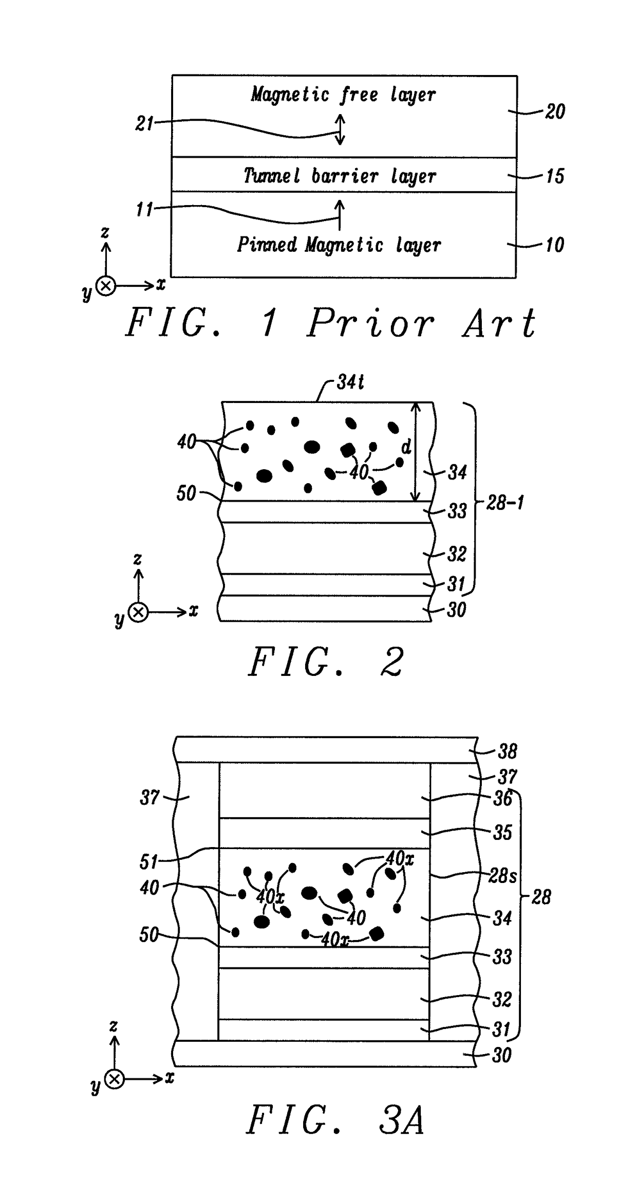
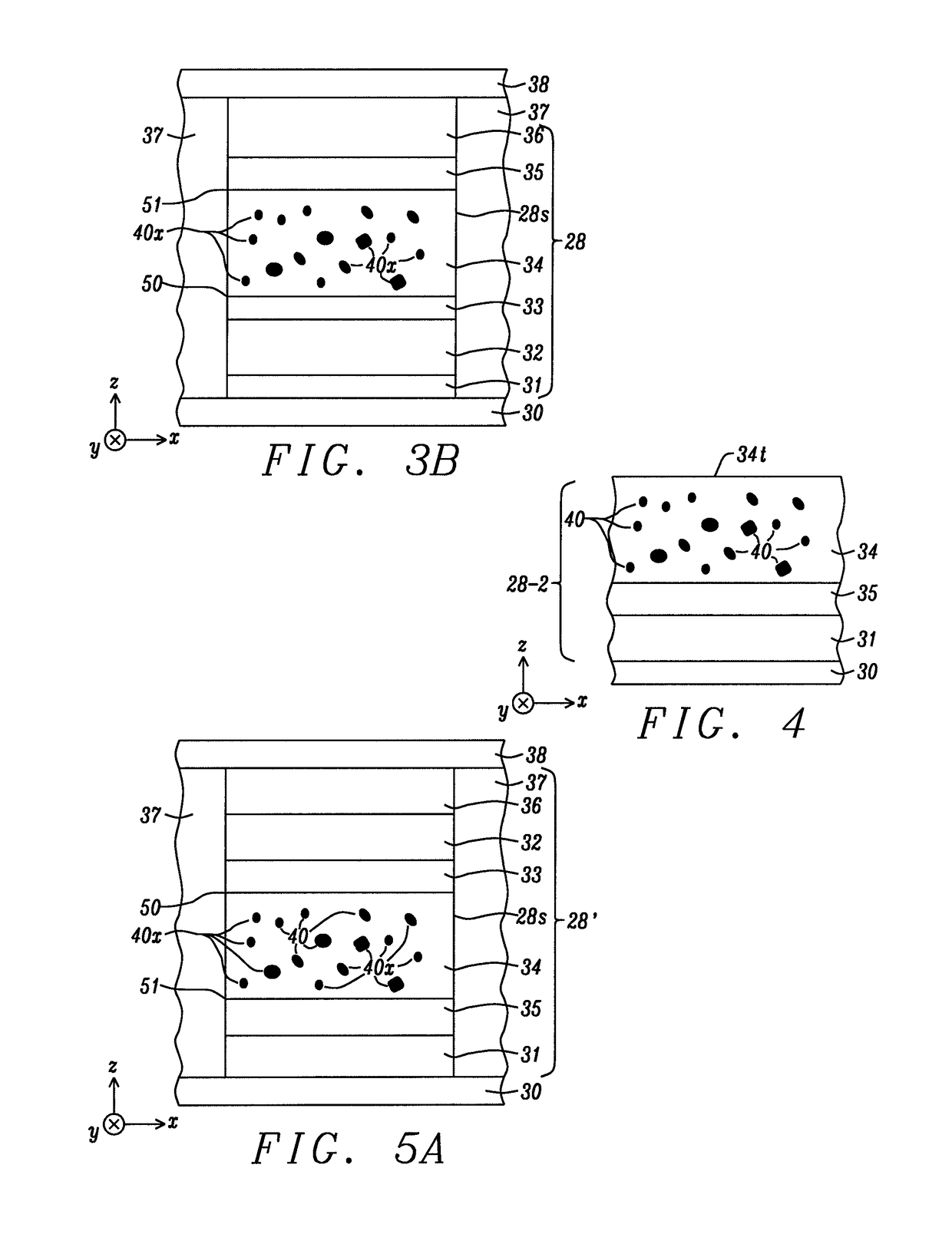
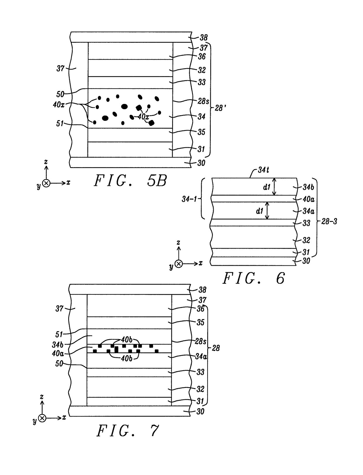
[0047]The present disclosure is based on the discovery that perpendicular surface anisotropy may be enhanced in a PMA-MTJ by including metal oxide clusters, or one or a plurality of non-stoichiometric metal oxide layers within a free layer while preserving MR ratio and achieving an acceptable RA value. The free layer preferably has top and bottom surfaces that each form an interface with a metal oxide layer to lower switching current and increase thermal stability. Although the exemplary embodiments depict MTJ elements with bottom spin valve and top spin valve configurations, the present disclosure also encompasses a MTJ having a dual spin valve structure as appreciated by those skilled in the art. The PMA-MTJ may be incorporated in a MRAM, STT-MRAM or another spintronic device such as a spin torque oscillator, spin hall effect device, magnetic sensor, and a biosensor. The terms interfacial perpendicular anisotropy and perpendicular surface anisotropy may be used interchangeably.

[00...


PUM


Abstract

A magnetic tunnel junction (MTJ) is disclosed wherein first and second interfaces of a free layer (FL) with a first metal oxide (Hk enhancing layer) and second metal oxide (tunnel barrier), respectively, produce perpendicular magnetic anisotropy (PMA) to increase thermal stability. In some embodiments, a continuous or discontinuous metal (M) or MQ alloy layer within the FL reacts with scavenged oxygen to form a partially oxidized metal or alloy layer that enhances PMA and maintains acceptable RA. M is one of Mg, Al, B, Ca, Ba, Sr, Ta, Si, Mn, Ti, Zr, or Hf, and Q is a transition metal, B, C, or Al. Methods are also provided for forming composite free layers where interfacial perpendicular anisotropy is generated therein by contact of the free layer with oxidized materials.

Description

[0001]This is a Divisional application of U.S. patent application Ser. No. 15 / 461,779, filed on Mar. 17, 2017, which is herein incorporated by reference in its entirety, and assigned to a common assignee.RELATED PATENT APPLICATIONS[0002]This application is related to the following: Ser. No. 15 / 196,807, filing date Jun. 29, 2016; U.S. Pat. Nos. 9,006,704; and 9,048,411, which are assigned to a common assignee and herein incorporated by reference in their entirety.TECHNICAL FIELD[0003]The present disclosure relates to a magnetic element comprised of a free layer that interfaces with a tunnel barrier layer and an Hk enhancing layer, and wherein the free layer comprises MgO in the form of clusters or non-stoichiometric MgO in a continuous layer that promote higher perpendicular magnetic anisotropy (PMA), better thermal stability, and lower switching current for spintronic applications.BACKGROUND[0004]Magnetoresistive Random Access Memory (MRAM), based on the integration of silicon CMOS ...

Claims


Application Information

Patent Timeline
IPC IPC(8): H01L43/10G11C11/16H01L43/12H01L43/08H01F10/32H01F41/32H01F10/14H01F10/16
CPCH01L43/10G11C11/161H01F10/142H01F10/16H01L43/12H01F10/3254H01F10/3286H01F41/32H01L43/08H01F10/32H10N50/10H10N50/01H10N50/85H10N50/80
Inventor IWATA, JODI MARIJAN, GUENOLETONG, RU-YINGWANG, PO-KANG
Owner TAIWAN SEMICON MFG CO LTD
Why Eureka
Try Eureka