Method for forming carbonaceous material protrusion and carbonaceous material protrusion
A carbon-based and resist technology, which is applied to the formation of carbon-based material protrusions and the field of carbon-based material protrusions, can solve unknown, undiscovered and other problems, and achieve small height deviation, increased aspect ratio, and good height uniformity. Effect
- Summary
- Abstract
- Description
- Claims
- Application Information
AI Technical Summary
Problems solved by technology
Method used
Image


Examples
Embodiment 1
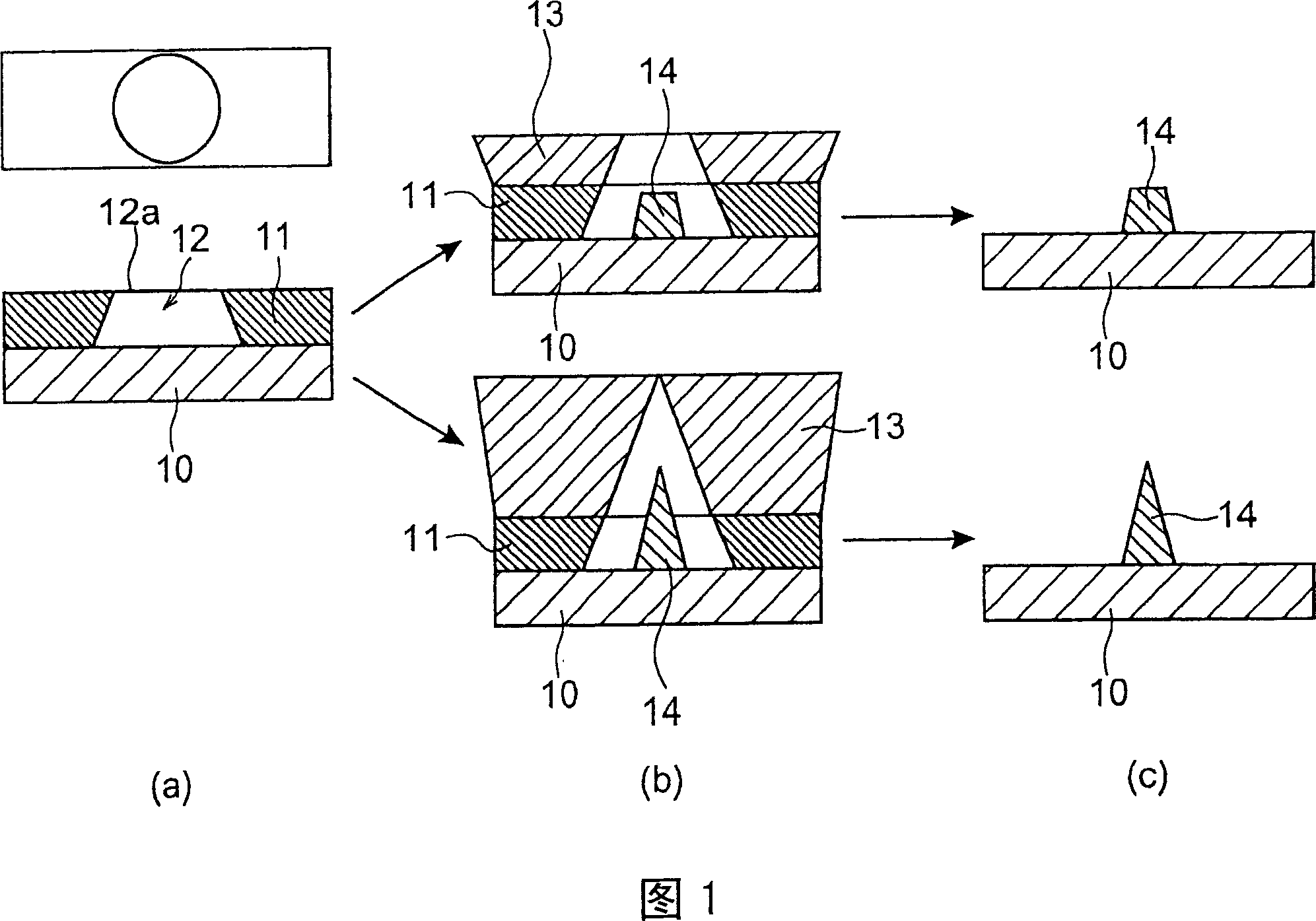
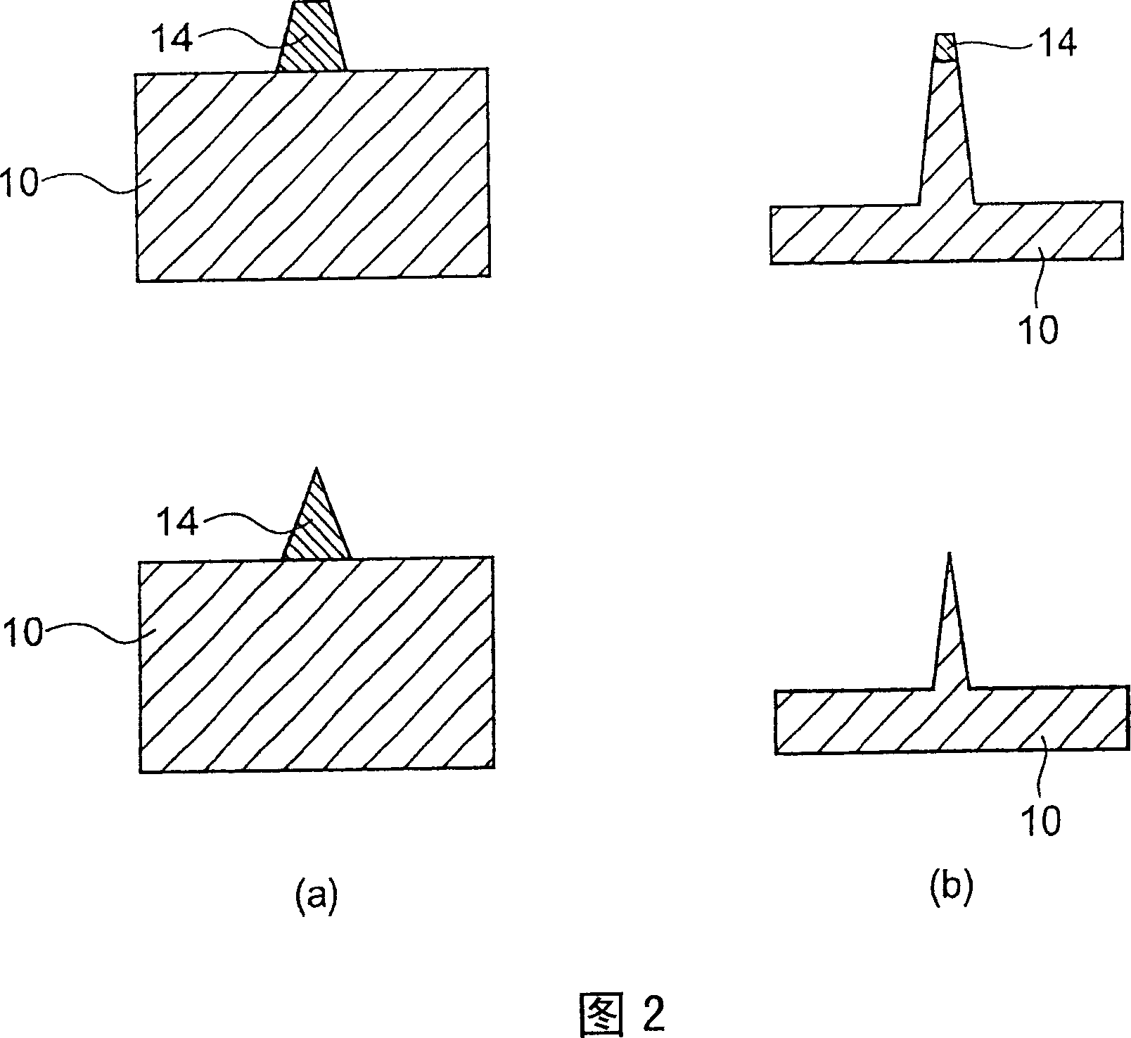
[0078] High-pressure synthetic single crystal diamond substrates (100) and CVD polycrystalline diamond wafer substrates planarized to a few nanometers or less by grinding were prepared, resist coating for electron beam lithography was performed, and electron beam exposure was performed to form inverted tapered holes (Refer to part (a) of FIG. 1). A metal film made of any one of Au, Mo, Pt, and Al is vapor-deposited thereon, and then the resist is removed to lift off the metal film (see part (c) of FIG. 1 ). When the diamond is etched using this as a mask, a diamond with a very sharp apex angle can be formed as shown in parts (a) and (b) of FIG. 4 . Part (a) of FIG. 4 shows a shape formed by a truncated cone mask, or a protrusion of a shape formed by stopping etching before the mask material disappears by using a cone mask. Part (b) of FIG. 4 shows the sharp-shaped protrusion etched to the end of the cone mask. According to this experiment, very fine sharp protrusions can be ...
Embodiment 2
[0082]A high-pressure synthetic single crystal diamond substrate (100), a CVD polycrystalline diamond wafer substrate, and a SiC substrate planarized to a few nm or less by grinding are prepared. Samples in which ion implantation of inert gas and nitrogen gas were respectively performed on these substrates were produced. In addition, some of these samples were subjected to high-temperature annealing (1500° C., 1800° C.) in vacuum, and the rest of these samples, which were not subjected to ion implantation, were treated at high temperature. A conductive black layer considered to be graphite was formed on the surface of any sample. Protrusion shape masks were formed on these samples by the same method as in Example 1. When the carbon-based material is etched using this as a mask, protrusions of the carbon-based material with very sharp apex angles appear as shown in parts (a) and (b) of FIG. 4 . Since the carbon-based material on the surface was already removed by etching, a c...
Embodiment 3
[0084] High-pressure synthetic single crystal diamond substrates (100) and CVD polycrystalline diamond wafer substrates planarized to a few nanometers or less by grinding were prepared, resist coating for electron beam lithography was performed, and electron beam exposure was performed to form inverted tapered holes (Refer to (a) of FIG. 1). SiO 2 Evaporate SiO as raw material by EB evaporation method x film, followed by removal of the resist, the SiO x Membrane lift-off (see part (c) of FIG. 1 ). Although SiO x The composition of the film is towards SiO x When a trace amount of oxygen is introduced into the film, it is close to SiO 2 , however, when processed in an inert gas or in a high vacuum, the oxygen composition of the film is very small. The composition is represented in FIG. 7 . When the diamond is etched using this mask, it produces diamond pillars with very sharp tips. It was confirmed that diamond protrusions were generated even when a metal mask was not us...
PUM
| Property | Measurement | Unit |
|---|---|---|
| angle | aaaaa | aaaaa |
| angle | aaaaa | aaaaa |
| thickness | aaaaa | aaaaa |
Abstract
Description
Claims
Application Information
 - R&D
- Intellectual Property
- Life Sciences
- Materials
- Tech Scout
- Unparalleled Data Quality
- Higher Quality Content
- 60% Fewer Hallucinations
Browse by: Latest US Patents, China's latest patents, Technical Efficacy Thesaurus, Application Domain, Technology Topic, Popular Technical Reports.
© 2025 PatSnap. All rights reserved.Legal|Privacy policy|Modern Slavery Act Transparency Statement|Sitemap|About US| Contact US: help@patsnap.com