
Preparation method of composite hard material

A technology of composite hard materials and hard alloy blocks, which is applied in the direction of metal material coating process, coating, fusion spraying, etc. Performance degradation and other problems, to achieve the effect of omitting mold engraving and layout time, simple and fast production process, and good wear resistance

Pending Publication Date: 2022-02-01
湖南威盾新材料技术有限责任公司
View PDF4 Cites 0 Cited by
  • Summary
  • Abstract
  • Description
  • Claims
  • Application Information

AI Technical Summary

Problems solved by technology

[0004] However, the matrix (metal material part) of the composite hard material prepared by vacuum brazing has experienced high temperature in the vacuum furnace and is in an annealed state, resulting in a sharp decline in its mechanical properties, and the product is easily deformed and broken during use; There are many cracks on the surface of the composite hard material prepared by laser cladding, and the thickness of a single cladding is limited (generally less than 1mm). The prepared composite hard material has a low bonding strength between the substrate and the sprayed layer (mechanical interlocking mode), resulting in no violent impact and force between points and surfaces, and its thickness is limited (generally less than 0.5mm) ; The composite hard material substrate (metal material part) prepared by flame spray welding is micro-metallurgically bonded to the wear-resistant layer, which is prone to peeling off when subjected to high load impact, and the process is highly dependent on the operator , quality stability is difficult to guarantee

Method used


Image

  • Preparation method of composite hard material
  • Preparation method of composite hard material
  • Preparation method of composite hard material

Examples


preparation example Construction

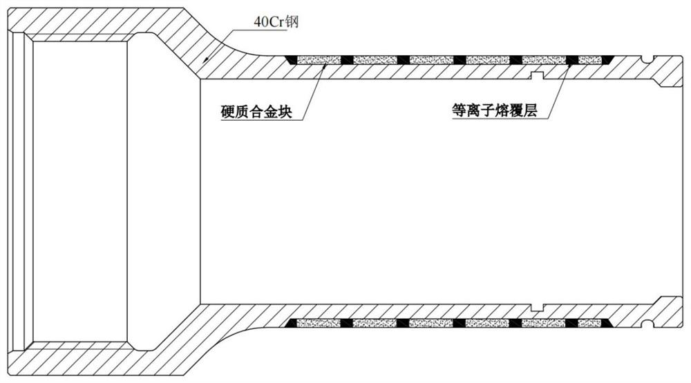
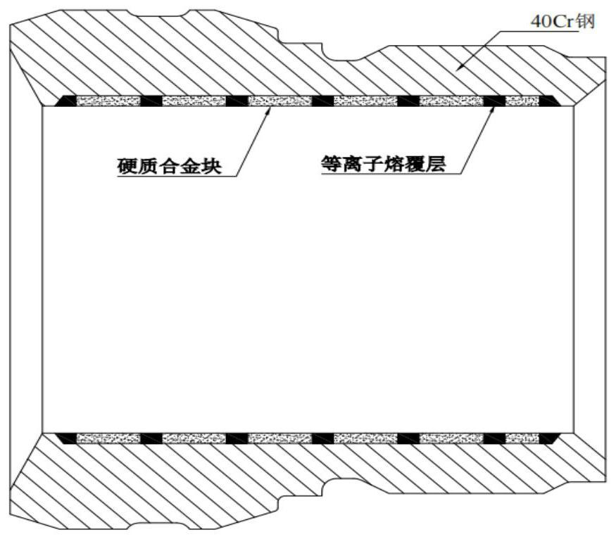
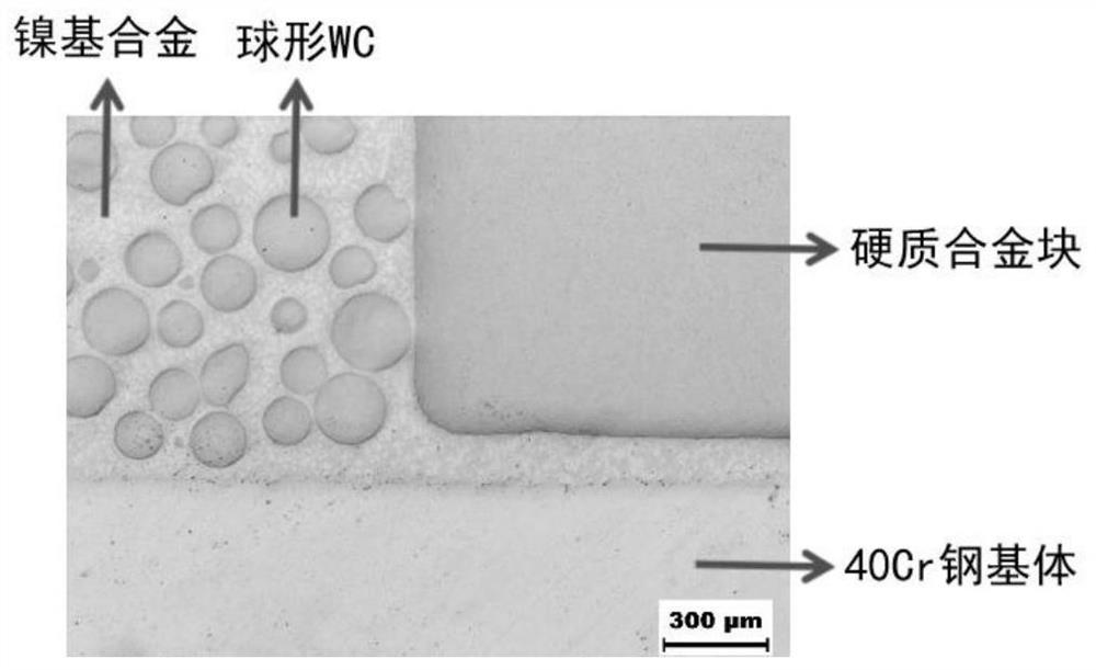
[0034] According to a general technical idea of ​​the present invention, such as Figure 1-3 As shown, a kind of preparation method of composite hard material is provided, comprising the following steps:

[0035] According to the design requirements, the metal substrate can be made of steel, and the grade, performance, shape, size and distribution of the hard alloy block on the surface of the steel should be selected properly. The shape of the steel can be flat or curved;

[0036] Apply a layer of nickel-based alloy coating on the steel surface by means of flame spraying;

[0037] Using custom-made automated "quick discharge" equipment, the hard alloy block is placed on the surface of the above-mentioned nickel-based alloy coating, and then a large current is applied instantaneously to make the hard alloy block and the nickel-based alloy coating instantly heat up, and the temperature is higher than The melting point of nickel-based alloy coating is lower than the liquidus poi...

Embodiment 1

[0048] On the outer surface of the tubular 40Cr substrate whose size is Φ120mm outer diameter*Φ260mm inner diameter*70mm long, use powdered nickel-based powder as raw material, and use flame spraying method to coat a layer of nickel-based alloy coating, the thickness of which is controlled at 0.08mm .

[0049] The above-mentioned 40Cr substrate coated with the nickel-based alloy coating on the surface is placed on the fixture of the automatic rapid discharge equipment. The automatic rapid discharge equipment is equipped with an automatic conveying and holding device for cemented carbide blocks. The cemented carbide blocks are WD11C grades provided by Weidun New Material Technology Co., Ltd., and the size is 12mm long*5mm wide*3mm thick. According to the customer's requirements, combined with the outer diameter and length of the substrate, determine the horizontal and vertical spacing between the cemented carbide blocks as 3.3mm and 2.5mm respectively, and set them in the PLC p...

Embodiment 2

[0057] On the surface of the inner wall of the tubular 40Cr matrix with a size of Φ150mm outer diameter*Φ70mm inner diameter*165mm long, a layer of nickel-based alloy coating is coated with powdered nickel-based powder as raw material by flame spraying, and its thickness is controlled at 0.1mm.

[0058] The above-mentioned 40Cr substrate coated with the nickel-based alloy coating on the surface is placed on the fixture of the automatic rapid discharge equipment. The automatic rapid discharge equipment is equipped with an automatic conveying and holding device for cemented carbide blocks. The cemented carbide blocks are WD11C grades provided by Weidun New Material Technology Co., Ltd., and the size is 12mm long*5mm wide*3mm thick. According to the customer's requirements, combined with the outer diameter and length of the substrate, determine the horizontal and vertical spacing between the cemented carbide blocks as 3.5mm and 3mm respectively, and set them in the PLC program on ...


PUM

PropertyMeasurementUnit
Thicknessaaaaaaaaaa
Lengthaaaaaaaaaa
Widthaaaaaaaaaa

Abstract

The invention discloses a preparation method of a composite hard material, and belongs to the technical field of composite materials. The method comprises the following steps: spraying a nickel-based alloy coating on the surface of a metal matrix by flame; fixing a hard alloy block and the metal matrix through fusion welding; and cladding a metal ceramic material in gaps among the hard alloy blocks by adopting a plasma transferred arc cladding technology to obtain the composite hard material. According to the invention, the plasma transferred arc cladding technology is adopted to clad the metal ceramic material in the gaps between the hard alloy blocks, and the hard alloy blocks and the metal base material form metallurgical bonding, so that the compounding of the metal base material, the hard alloy, the nickel-based alloy and the tungsten carbide ceramic particles is realized. The obtained composite hard material has the advantages of lower porosity, fewer cracks, higher bonding strength between the plasma transferred arc cladding layer and the hard alloy block and between the plasma transferred arc cladding layer and the metal base material, and excellent wear resistance and impact resistance.

Description

technical field [0001] The invention belongs to the technical field of composite materials, in particular to a preparation method of composite hard materials. Background technique [0002] Cemented carbide is often used to prepare cutting tools due to its high hardness and wear resistance, and is known as the "teeth" of industry. Its industrial application is not limited to cutting tools, but also such as mining alloys and wear-resistant parts. However, due to its high brittleness, difficulty in processing, and high cost, the application of cemented carbide in some tool parts in some fields is greatly limited, especially some tools that have both wear and impact and cold and heat cycles. under harsh working conditions. For example, "radial bearings" and "rolling guides" for high-speed wire laying machines are used in screw motors in the field of oil and gas drilling and production. With the continuous development of technology, the emergence of composite hard materials wi...

Claims


Application Information

Patent Timeline
IPC IPC(8): C23C4/129C23C4/06C23C4/18C23C24/10C22C29/08C22C19/03C23C4/16
CPCC23C4/129C23C4/06C23C4/18C23C24/103C22C19/03C22C29/067C22C29/08C23C4/16
Inventor 刘少存
Owner 湖南威盾新材料技术有限责任公司
Learn More