Inductor and manufacturing method thereof

A manufacturing method and inductor technology, which is applied in the direction of inductor/transformer/magnet manufacturing, inductors, fixed inductors, etc., can solve the problems of not being able to meet the power supply requirements of servers, increase inductance loss, and affect inductor efficiency, so as to achieve low loss and reduce The effect of high DC resistance and magnetic permeability

Inactive Publication Date: 2021-04-06
HENGDIAN GRP DMEGC MAGNETICS CO LTD
View PDF5 Cites 3 Cited by
  • Summary
  • Abstract
  • Description
  • Claims
  • Application Information

AI Technical Summary

Problems solved by technology

[0003] The integrally formed inductors produced by the above method are generally used in circuits with lower frequency requirements below 200Khz. However, with the advancement of 5G technology, the power supply unit in the server chip needs to use higher frequency integratedly formed inductors. The frequency is between 500Khz and Above, as the frequency rises, the inductance loss produced by the traditional one-piece inductor process increases significantly, causing the inductor to heat up, which seriously affects the efficiency of the inductor. The traditional one-piece inductor process produces inductors that are no longer suitable for server power supply. need
[0004] In addition, in the prior art, in order to reduce the DC resistance of the inductance, the method of increasing the overall thickness or width of the conductor is usually adopted, but the two ends of the conductor are exposed outside the magnetic core as terminals, and the parts used as terminals need to be bent , the overall thickness of the conductor is thicker, which makes it difficult to bend the two ends of the conductor as terminals, and the overall width of the conductor is larger, making the side wall easy to crack after the inductor is formed.

Method used


Image

  • Inductor and manufacturing method thereof
  • Inductor and manufacturing method thereof
  • Inductor and manufacturing method thereof

Examples


Embodiment 1

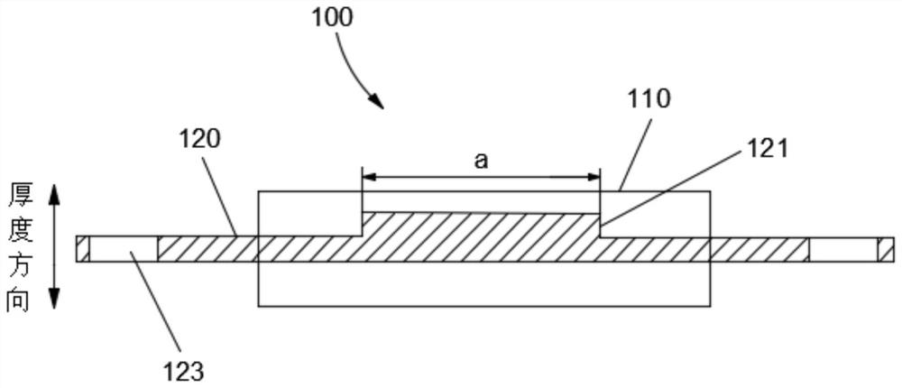
[0084] 1) Stamping or casting metal materials such as figure 1 The shape shown, forms the conductor 120, the length of the thicker part in the middle of the conductor 120 is 10.0mm;

[0085] 2) Select a magnetic powder with a certain particle size ratio, and add a passivating agent for passivation;

[0086] 3) Add a certain proportion (0.5-2.5% by mass) of epoxy resin or silane resin and other glues in the passivated powder;

[0087] 4) After adding glue, the powder is dried, baked, crushed and sieved to form a fluid powder with a certain particle size;

[0088] 5) Encapsulate the conductor 120 designed in 1) and the powder made in 4) (that is, perform cold pressing and / or hot pressing) to obtain a semi-finished inductor;

[0089] 6) Sintering and annealing the semi-finished inductor obtained in 5) according to the temperature shown in Table 1 below:

[0090] Table 1

[0091]

[0092] In the table, "position" refers to different positions in the sintering equipment, the...

Embodiment 2

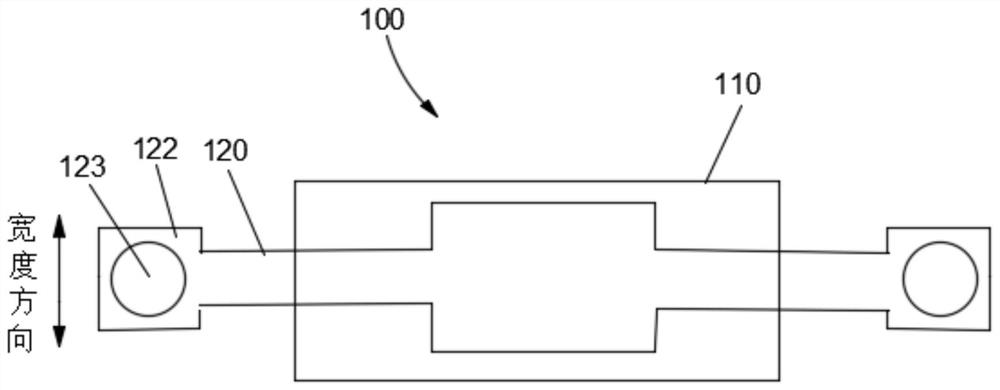
[0106] The product in the embodiment of the present invention 2 adopts such as Figure 4 Shown product, repeat step 2) to 10) among the embodiment 1;

[0107] Comparing the characteristics of the product in Example 2 of the present invention with Comparative Example 1 and Comparative Example 2, it can be verified that the product in Example 2 of the present invention has better DCR characteristics.


PUM

PropertyMeasurementUnit
lengthaaaaaaaaaa
lengthaaaaaaaaaa

Abstract

The invention discloses an inductor and a manufacturing method thereof. The inductor comprises a magnetic core and a conductor, the middle part of the conductor is arranged in the magnetic core, two ends of the conductor are exposed outside the magnetic core, the middle part of the conductor is thicker than the two ends of the conductor, and / or the middle part of the conductor is wider than the two ends of the conductor to reduce the direct-current resistance of the inductor. The manufacturing method comprises the following steps of A, manufacturing the conductor, B, putting the conductor into magnetic powder, and pressing to form an inductor semi-finished product, C, sintering, annealing and curing the inductor semi-finished product, and D, processing the two ends of the conductor, removing redundant parts, and bending the two ends of the conductor. According to the inductor, the middle part of the conductor is thickened and / or widened, so that the direct-current resistance of the inductor can be effectively reduced. In the inductor manufacturing method, through a sintering annealing process, the inductance value of the inductor can be improved, the size of the inductor can be reduced, the loss and heating of the inductor under high-frequency use can be reduced, and the efficiency of the inductor can be improved.

Description

technical field [0001] The invention relates to the technical field of inductor manufacturing, in particular to an inductor and a manufacturing method thereof. Background technique [0002] The existing one-piece inductor includes a magnetic core and a winding body. The magnetic core is die-cast by embedding the winding body in metal magnetic powder. The winding body is usually a single-layer or multi-layer coil covered with enamelled film, or is A single straight conductor (such as copper sheet). Coils and conductors are pressed in the middle of the magnetic powder by cold process or hot process, and then the glue in the magnetic powder is cured by the baking process (baking peak temperature 140-180 ℃), forming an inductive product with a certain strength. [0003] The integrally formed inductors produced by the above method are generally used in circuits with lower frequency requirements below 200Khz. However, with the advancement of 5G technology, the power supply unit i...

Claims


Application Information

Patent Timeline
Patent Type & Authority Applications(China)
IPC IPC(8): H01F27/28H01F41/00H01F17/04
CPCH01F27/2847H01F27/2852H01F41/00H01F17/04H01F2017/048
Inventor 王林科郭宾
Owner HENGDIAN GRP DMEGC MAGNETICS CO LTD
Why Eureka
Try Eureka