A kind of preparation method of 3D printing monolithic silicon carbide heat shield
A 3D printing, heat shield technology, applied in lighting and heating equipment, manufacturing tools, furnaces, etc., can solve problems such as reducing heat insulation performance, and achieve the effects of low thermal conductivity, reduced conduction loss, and good controllability
- Summary
- Abstract
- Description
- Claims
- Application Information
AI Technical Summary
Problems solved by technology
Method used
Image
Examples
Embodiment 1
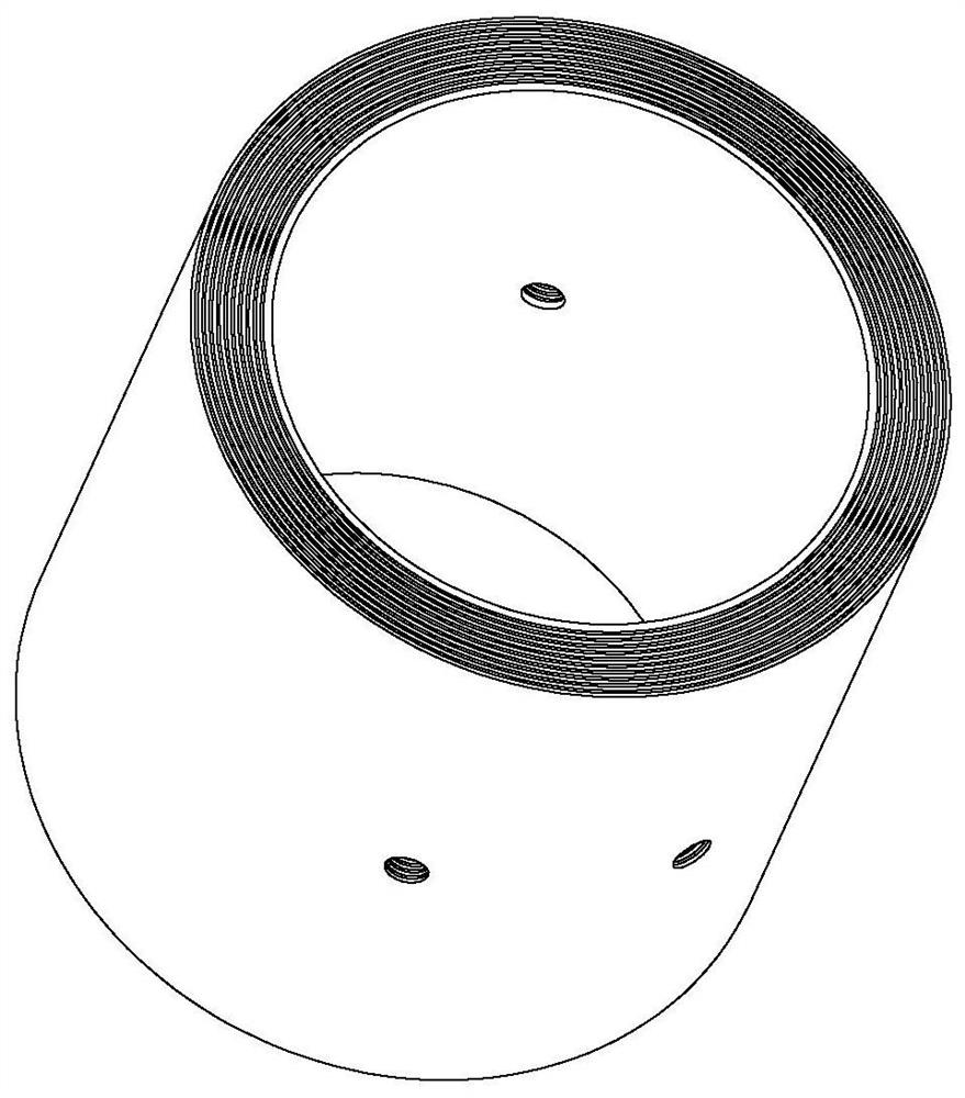
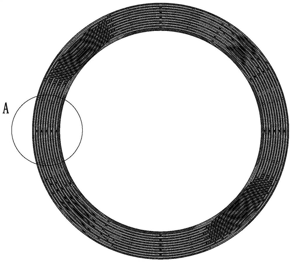
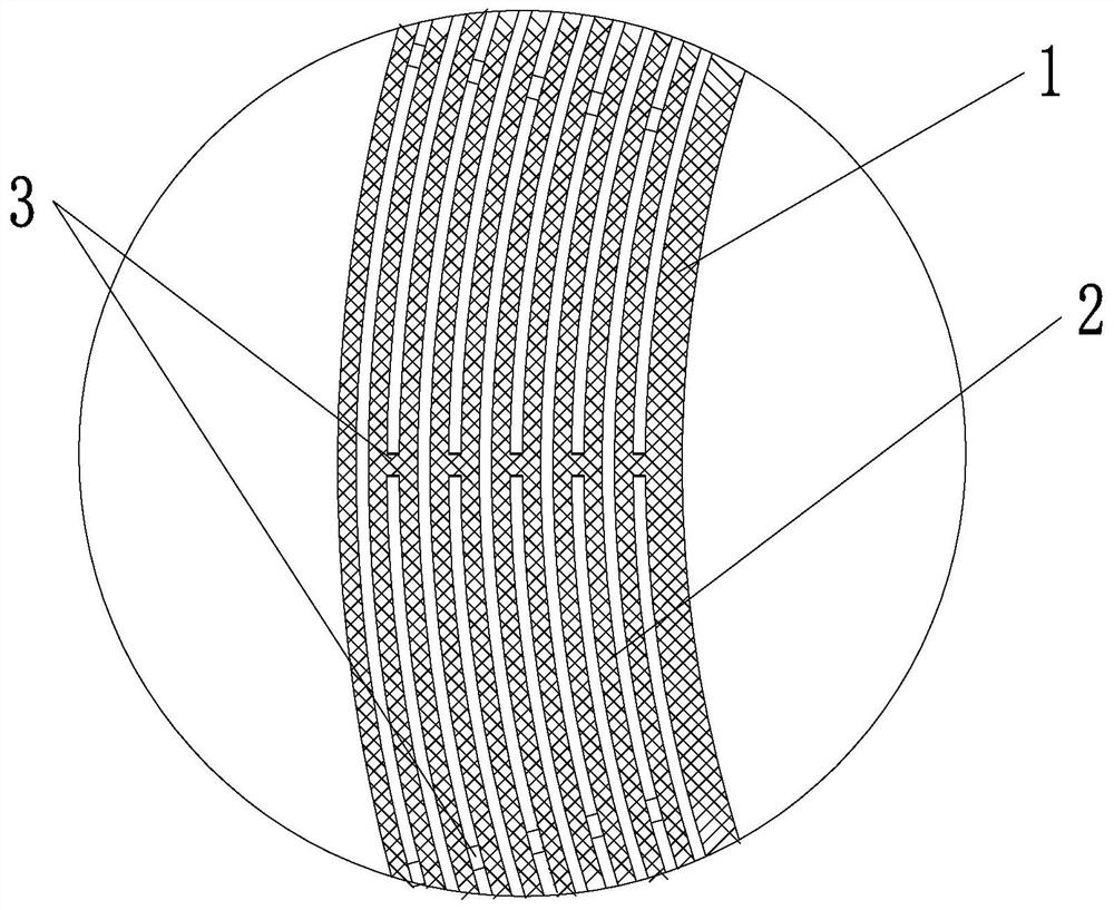
[0033] like Figure 1-3 As shown, a preparation method of a 3D printed monolithic silicon carbide heat shield includes the following steps:
[0034] (1) Slice and layer the model of the designed heat shield, determine the printing program according to the structure, and import the program into the 3D printing equipment program; The ionized water was evenly mixed and ball-milled for 2 hours, and then the ball-milled slurry was vacuum-defoamed in a vacuum defoamer for 10 minutes to obtain ceramic slurry;
[0035] The proportion of silicon carbide ceramic powder is 50wt%, the proportion of dispersant is 0.1wt%, the proportion of binder is 0.1wt%, the proportion of deionized water is 49.79wt%, and the proportion of defoaming agent is 0.01%. The dispersing agent adopts ammonia water, and the binder adopts sodium carboxymethyl cellulose; (3) adding the prepared ceramic slurry into the barrel of the 3D printer, under the control of the printing program described in step (1) The cer...
Embodiment 2
[0037] like Figure 4-6 As shown, a preparation method of a 3D printed monolithic silicon carbide heat shield includes the following steps:
[0038](1) slice and layer the model of the designed heat shield, determine the printing program according to the structure, and import the program into the 3D printing equipment program; (2) combine silicon carbide powder, dispersant, binder, Ionized water was mixed evenly and ball milled for 12 hours, and then the ball milled slurry was vacuum defoamed for 35 minutes in a vacuum defoaming machine to obtain a ceramic slurry; the proportion of silicon carbide ceramic powder was 60wt%, and the proportion of dispersant was 5wt%. The binder ratio is 5wt%, the deionized water ratio is 26wt%, and the defoamer ratio is 4%. The dispersant is polyethyleneimine, and the binder is gelatin. (3) Add the prepared ceramic slurry into the barrel of the 3D printer, extrude the ceramic slurry into a filamentary unit under the control of the printing pro...
Embodiment 3
[0040] like Figure 7-9 Shown, a kind of preparation method of 3D printing monolithic silicon carbide heat shield comprises the following steps:
[0041] (1) slice and layer the model of the designed heat shield, determine the printing program according to the structure, and import the program into the 3D printing equipment program; (2) combine silicon carbide powder, dispersant, binder, Ionized water is mixed evenly and ball milled for 1-24 hours, and then the ball-milled slurry is subjected to vacuum defoaming in a vacuum defoaming machine for 60 minutes to obtain a ceramic slurry; the proportion of silicon carbide ceramic powder is 12wt%, and the proportion of dispersant is 10wt %, the binder ratio is 20wt%, the deionized water ratio is 50wt%, and the defoamer ratio is 8%. The dispersant is sodium tripolyphosphate, and the binder is dextrin. (3) Add the prepared ceramic slurry into the barrel of the 3D printer, extrude the ceramic slurry into a filamentary unit under the ...
PUM
| Property | Measurement | Unit |
|---|---|---|
| thickness | aaaaa | aaaaa |
| thickness | aaaaa | aaaaa |
| diameter | aaaaa | aaaaa |
Abstract
Description
Claims
Application Information
 - R&D
- Intellectual Property
- Life Sciences
- Materials
- Tech Scout
- Unparalleled Data Quality
- Higher Quality Content
- 60% Fewer Hallucinations
Browse by: Latest US Patents, China's latest patents, Technical Efficacy Thesaurus, Application Domain, Technology Topic, Popular Technical Reports.
© 2025 PatSnap. All rights reserved.Legal|Privacy policy|Modern Slavery Act Transparency Statement|Sitemap|About US| Contact US: help@patsnap.com


