
A composite lithium ion battery separator

A lithium-ion battery, ion battery technology, applied in secondary batteries, battery pack parts, circuits, etc., can solve the problem of wettability, porosity, low electrolyte absorption rate, unsatisfactory comprehensive performance of the diaphragm, and thermal shrinkage of the diaphragm. Reduction and other problems, to achieve the effect of excellent contact angle and liquid absorption rate, conducive to transmission, and excellent air permeability

Inactive Publication Date: 2019-01-18
QINGDAO UNIV
View PDF5 Cites 0 Cited by
  • Summary
  • Abstract
  • Description
  • Claims
  • Application Information

AI Technical Summary

Problems solved by technology

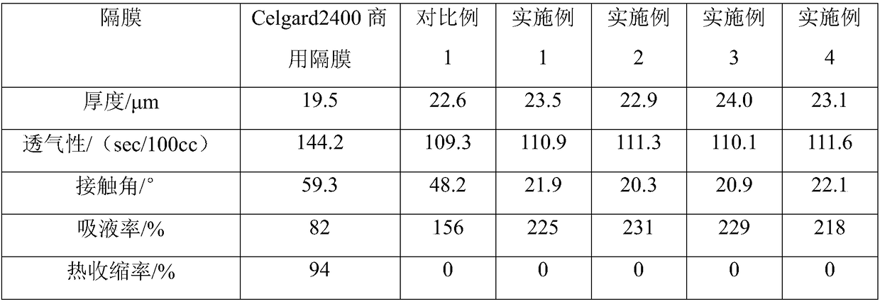
At present, polyolefin microporous membranes are widely used in commercial lithium battery separators, such as polyethylene and polypropylene separators, but the thermal stability of this separator is poor, and the wettability, porosity and electrolyte absorption rate are relatively low. Low, there are security risks, not enough to meet people's requirements
[0004] Chinese invention patent 201810169305.3 discloses a lithium-ion battery separator, including a PP / PE / PP porous film substrate and a cyclodextrin polymer layer on the surface of the PP / PE / PP porous film substrate. The preparation method includes the following steps: The cyclodextrin polymer slurry is evenly coated on the PP / PE / PP porous film substrate to form a cyclodextrin polymer layer, and after drying, a lithium-ion battery separator is obtained; this invention mainly realizes the reduction of the thermal shrinkage rate of the separator, However, the preparation process is complicated, and various additives are added, and the overall performance of the separator is still not ideal.
[0005] Chinese invention patent 201610363502X discloses a method for preparing a separator for lithium-ion batteries. Polyethylene, polycarbonate, maleic anhydride resin, hydroxyethyl methacrylate, titanium dioxide, polylactic acid, polycyclic lactone and The plasticizer is heated and stirred, and extruded to form a film to obtain a base film; then immersed in a mixed solution composed of hypromellose, polyethylene glycol, white carbon black and zirconia; to obtain a separator for a lithium ion battery; the method A wide variety of raw materials and additives are required, but only improve the mechanical and electrical properties of the product

Method used


Image

  • A composite lithium ion battery separator

Examples


Embodiment 1

[0020] Prepare a polytetrafluoroethylene DMF solution with a mass concentration of 6%, and take an appropriate amount of the solution for electrospinning. The electrospinning parameters are as follows: the spinning voltage is 18kV, the propulsion rate is 0.015mL / min, the spinning receiving distance is 25cm, and the syringe The needle is 10#, and the polytetrafluoroethylene fiber membrane is obtained by spinning at room temperature for 8 hours; the bisphenol A polycarbonate DMF solution with a mass concentration of 6% is prepared, and the polytetrafluoroethylene fiber membrane is soaked in it for 2 hours, and then Take it out and put it in a vacuum drying oven and dry it at 100°C for 24 hours to obtain a polytetrafluoroethylene / polycarbonate composite fiber membrane. After determination, the mass fraction of polytetrafluoroethylene is 87%, and the mass fraction of polycarbonate is 13%.

Embodiment 2

[0022] Prepare a polytetrafluoroethylene DMF solution with a mass concentration of 15%, and take an appropriate amount of the solution for electrospinning. The electrospinning parameters are as follows: the spinning voltage is 18kV, the propulsion rate is 0.015mL / min, the spinning receiving distance is 25cm, and the syringe The needle is 10#, spinning at room temperature for 2h to obtain a polytetrafluoroethylene fiber membrane; prepare a tetrachlorobisphenol A polycarbonate DMF solution with a mass concentration of 2%, put the polytetrafluoroethylene fiber membrane into it and soak for 5h , and then take it out and put it into a vacuum drying oven and dry it at 100°C for 24 hours to obtain a polytetrafluoroethylene / polycarbonate composite fiber membrane. After determination, the mass fraction of polytetrafluoroethylene is 93%, and the mass fraction of polycarbonate is 7%.

Embodiment 3

[0024] Prepare a polytetrafluoroethylene DMF solution with a mass concentration of 12%, and take an appropriate amount of the solution for electrospinning. The electrospinning parameters are as follows: the spinning voltage is 18kV, the propulsion rate is 0.015mL / min, and the spinning receiving distance is 25cm. The needle is 10#, and the polytetrafluoroethylene fiber membrane is obtained by spinning at room temperature for 6 hours; the tetrabromobisphenol A polycarbonate DMF solution with a mass concentration of 5% is prepared, and the polytetrafluoroethylene fiber membrane is soaked in it for 4 hours , and then take it out and put it into a vacuum drying oven and dry it at 100°C for 24 hours to obtain a polytetrafluoroethylene / polycarbonate composite fiber membrane. After determination, the mass fraction of polytetrafluoroethylene is 80%, and the mass fraction of polycarbonate is 20%.


PUM


Abstract

The invention belongs to the technical field of lithium ion batteries, in particular to a composite lithium ion battery separator, which is a polytetrafluoroethylene / polycarbonate composite fiber membrane with a skin-core structure; In the skin-core structure, polytetrafluoroethylene is the core and polycarbonate is the skin; 80 to 95 percent of polytetrafluoroethylene and 5 to 20 percent of polycarbonate in that polytetrafluoroethylene / polycarbonate composite fib membrane by mass fraction; The polytetrafluoroethylene / polycarbonate composite fiber membrane is prepared by an electrospinning method, has rich pore channel structure and high porosity, has good gas permeability, is conducive to absorption of electrolyte, maintains ion transmission in the membrane, and improves charging and discharging efficiency of a lithium ion battery. Therefore, the lithium ion battery separator of the present invention exhibits excellent air permeability and thermal stability, remarkably improves affinity with the electrolyte, and is more excellent in contact angle and liquid absorption rate of the electrolyte.

Description

technical field [0001] The invention belongs to the field of functional materials, in particular to the technical field of lithium-ion battery diaphragms, in particular to a polytetrafluoroethylene / polycarbonate composite lithium-ion battery diaphragm. Background technique [0002] Lithium-ion batteries (LIBs) have the advantages of high voltage, high specific energy, long life, no memory effect, environmental friendliness, fast charging speed, and low self-discharge rate, and have become the most concerned and highest-yielding consumer battery species. The lithium-ion battery separator plays an important role in avoiding the contact between the positive and negative electrodes of the battery, retaining the electrolyte, and allowing lithium ions to pass through. Its performance will have a huge impact on the electrochemical performance of the lithium-ion battery. Therefore, it will be an important part of the future development of lithium-ion batteries to research and develo...

Claims


Application Information

Patent Timeline
Patent Type & Authority Applications(China)
IPC IPC(8): H01M2/16H01M2/14H01M10/0525D01D5/00D04H1/4382D04H1/728D01F6/08D01F6/64H01M50/414H01M50/44H01M50/489
CPCH01M10/0525D01D5/003D01D5/0092D01F6/08D01F6/64D04H1/4382D04H1/728H01M50/411H01M50/44H01M50/403Y02E60/10
Inventor 杜辉陈照军段雅静
Owner QINGDAO UNIV
Learn More