Variable gain audio-frequency amplifier

An audio amplifier, a variable technology, applied in audio amplifiers, amplifiers, power amplifiers, etc., can solve the problems of narrow frequency band and poor frequency characteristics of audio amplifiers, and achieve the effect of wide frequency bandwidth and good frequency characteristics

Pending Publication Date: 2017-09-19
韦炳伦
View PDF0 Cites 4 Cited by
  • Summary
  • Abstract
  • Description
  • Claims
  • Application Information

AI Technical Summary

Problems solved by technology

[0007] In order to solve the above problems, the present invention discloses a variable gain audio amplifier. The present invention has simple structure, scientific and reasonable design, and can effectively amplify the voltage in the audio circuit, so that the voltage gain can be adjusted at will, solving the problem of existing audio amplifiers. Problems with narrow IF bandwidth and poor frequency characteristics

Method used


Image

  • Variable gain audio-frequency amplifier
  • Variable gain audio-frequency amplifier
  • Variable gain audio-frequency amplifier

Examples


Embodiment 1

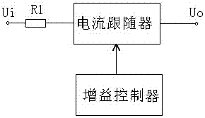
[0067] A variable gain audio amplifier is provided, including a resistor R1, a current follower and a gain controller; the resistor R1 is used to increase the input impedance of the current follower;

[0068] The current follower is a transistor common base amplifier;

[0069] The gain controller includes an input impedance controller, an input current controller and an output impedance controller;

[0070] The input impedance controller includes a potentiometer RP1;

[0071] The input current controller includes a potentiometer RP2 and a resistor R2, wherein one end of the potentiometer RP2 is connected to the input end of the input current controller, and the other end of the potentiometer RP2 is grounded; one end of the resistor R2 is connected to the input terminal of the input current controller. The input terminal is connected, and the other end of the resistor R2 is connected to the input terminal of the current follower;

[0072] The output impedance controller inclu...

Embodiment 2

[0082] The difference between this embodiment and Embodiment 1 is that the output stage of this embodiment is followed by a voltage follower to further increase the output power, as Figure 5b As shown, in order to ensure the output power, large-capacity capacitors should be used for the output DC blocking capacitors C4 and C5, and capacitors with different capacities can be connected in parallel to make them have very low impedance in the passband to ensure good frequency characteristics of the amplifier. J1 is the loudspeaker protection relay. J1 is disconnected when starting up. If the output potential of the amplifier deviates from the midpoint potential of capacitors C4 and C5, it will be charged and discharged through the resistor R9. When the two are equal, J1 will pull in and the amplifier will work normally.

Embodiment 3

[0084] The differences between this embodiment and embodiment 1 and embodiment 2 are: Figure 5b The withstand voltage of medium capacitors C4, C5, and C6 is higher than the power supply voltage. Figure 5c In the circuit form, the withstand voltage of capacitors C4, C5, and C6 only needs to be greater than half of the power supply voltage, but dual power supplies are used, and the negative terminals of the power supply are grounded. Capacitor C4 uses two electrolytic capacitor negative terminals connected together as a non-polar capacitor. , Capacitors C4, C5, and C6 all use large-capacity capacitors, and capacitors with different capacities can be connected in parallel to make them have very low impedance in the passband to ensure that the amplifier has good frequency characteristics.


PUM


Abstract

The invention discloses a variable gain audio-frequency amplifier. The variable gain audio-frequency amplifier comprises a resistor R1, a current follower and a gain controller, wherein the resistor R1 is used for amplifying input impedance of the current follower; the current follower is a transistor common-base amplifier; the gain controller comprises an input impedance controller, an input current controller and an output impedance controller; the input impedance controller comprises a potentiometer RP1; the input current controller comprises a potentiometer RP2 and a resistor R2; one end of the potentiometer RP2 is connected with an input end of the input current controller, and the other end of the potentiometer RP2 is grounded; one end of the resistor R2 is connected with the input end of the input current controller; and the other end of the resistor R2 is connected with the input end of the current follower. The variable gain audio-frequency amplifier has a scientific and reasonable design and can be used for effectively amplifying voltage in an audio-frequency circuit, so that voltage gain can be randomly adjusted, and the problems of an existing audio-frequency amplifier that the frequency band is narrow and the frequency property is poor are solved.

Description

technical field [0001] The invention relates to the field of audio amplification equipment, in particular to a variable gain audio amplifier. Background technique [0002] The existing audio amplifier has complex circuits, many components and parts, high cost and difficult design. Electron tubes, transistors and integrated circuits in the amplifying circuit are all nonlinear components, which are the source of nonlinear distortion in the amplifying circuit. Every time a nonlinear component is added, the nonlinear distortion may be increased. Although the introduction of negative feedback can reduce The nonlinear distortion of small amplifiers cannot fundamentally solve the problem. The best way is to use as few nonlinear components as possible in the amplifier circuit. To do this, two problems must be solved: one is that the amplifier gain must be large enough; the other is that the nonlinear distortion should be as small as possible. When no negative feedback is added or o...

Claims


Application Information

Patent Timeline
IPC IPC(8): H03F3/20H03F1/34H03G3/30H03G3/02
CPCH03F1/342H03F3/20H03G3/02H03G3/3005H03F2200/03
Inventor 韦炳伦
Owner 韦炳伦
Why Eureka
Try Eureka