
Method for preparing micro-frequency T-shaped power divider on metal substrate

A metal substrate and power divider technology, applied in metal material coating process, superimposed layer plating, coating, etc., can solve the problems affecting the performance of the structure, complex process, limited strength, etc., to reduce the failure of production Chance, reduce process steps, avoid fragile effects

Active Publication Date: 2019-03-05
DALIAN UNIV OF TECH
View PDF7 Cites 0 Cited by
  • Summary
  • Abstract
  • Description
  • Claims
  • Application Information

AI Technical Summary

Problems solved by technology

This method combines the process steps of ultraviolet lithography, sacrificial layer technology and packaging. The process is relatively complicated, and dimensional deviation is easy to occur during the packaging process, which affects the performance of the structure.
Moreover, the metallization of the structure in this method is done by sputtering process, which has limited strength compared with the metal structure obtained by electroforming process.
In addition, this method also uses silicon material as the substrate, which is also prone to the problem of fabrication failure due to substrate cracking

Method used


Image

  • Method for preparing micro-frequency T-shaped power divider on metal substrate
  • Method for preparing micro-frequency T-shaped power divider on metal substrate
  • Method for preparing micro-frequency T-shaped power divider on metal substrate

Examples


Embodiment Construction

[0034] The specific implementation manners of the present invention will be described in detail below in combination with the above technical solutions and accompanying drawings.

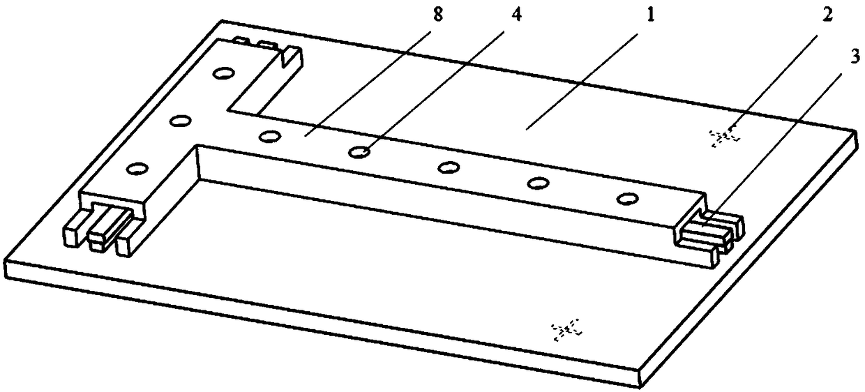
[0035] A micro-frequency T-shaped power splitter is prepared on the substrate, with figure 1 shown. The size of the base is 64×64×2mm. The specific steps to make the structure are as follows:

[0036] Step 1, pretreatment of the back of the substrate: Grinding and polishing the back of the substrate to make the surface roughness Ra less than 0.06 μm; wipe the substrate with acetone cotton balls and place them in acetone and ethanol for 15 minutes of ultrasonic cleaning respectively, and then use Rinse with deionized water and blow dry with nitrogen; put the cleaned substrate into a vacuum oven at 120°C for two hours and then cool to room temperature.

[0037] Step 2, make the back alignment mark: Spin-coat BN303 photoresist on the back of the substrate 1 with a thickness of 2-3 μm; through the pho...


PUM


Abstract

The invention relates to a method for preparing a micro-radio-frequency T-shaped power divider on a metal base, and belongs to the technical field of micro-manufacturing. A gel column used for supporting an inner conductor is manufactured by utilizing SU-8 negative photoresist on a copper base by adopting a UV-LIGA technology, then a graphic glue film is manufactured by utilizing AZ50XT positive photoresist, and structures of a metal frame, the inner conductor, a top cover and the like are obtained through a copper electroforming technology. Finally, the AZ50XT glue film is dissolved by utilizing acetone, and the T-shaped power divider is obtained. According to the method for preparing the micro-radio-frequency T-shaped power divider on the metal base, a traditional silicon base is abandoned and the metal base is used, the problem that the silicon base is prone to being broken into pieces in the manufacturing process is solved, further, a metal conducting layer is not needed to be sputtered on the base, and the process steps are reduced. Meanwhile, when the AZ50XT glue film is removed, heating is not needed, and heat stress cannot be generated inside the structure, so that the probability of failure of manufacturing is reduced.

Description

technical field [0001] The invention belongs to the field of micro-manufacturing technology, and relates to metal substrate micro-electroforming metal devices, in particular to a method for preparing a micro-frequency T-shaped power divider on a metal substrate based on UV-LIGA technology. Background technique [0002] Power splitter, that is, power divider, is a widely used signal transmission device. In recent years, with the development of microwave integrated circuit MMIC technology, the research and application of radio frequency electronic systems based on terahertz frequency band have received great attention. For radio frequency devices, their dimensional accuracy must reach the order of millimeters or even microns, which puts high demands on the processing technology. The MEMS process has become the best process choice for processing radio frequency devices because of its small size and compatibility with the MMIC process. This processing method has also attracted ...

Claims


Application Information

Patent Timeline
Patent Type & Authority Patents(China)
IPC IPC(8): C25D1/10C25D3/38C23C28/02
CPCC23C28/023C25D1/10C25D3/38
Inventor 杜立群李晓军李爰琪齐磊杰陶友胜赵明
Owner DALIAN UNIV OF TECH
Learn More