
Method and apparatus for preparing coated particles

A particle and coating technology, applied in the direction of coating particles, coatings, liquid chemical plating, etc., can solve the problems of time-consuming and inefficient processes

Inactive Publication Date: 2016-03-30
NEXANS
View PDF10 Cites 3 Cited by
  • Summary
  • Abstract
  • Description
  • Claims
  • Application Information

AI Technical Summary

Problems solved by technology

[0032] The methods disclosed in many of the prior art documents referred to above involve a relatively large number of steps which makes the process not only time consuming but also inefficient

Method used


Image

  • Method and apparatus for preparing coated particles
  • Method and apparatus for preparing coated particles
  • Method and apparatus for preparing coated particles

Examples


Embodiment approach

[0201] Preferably, the substrate particles used in the method of the first aspect of the present invention contain metal or semi-metallic materials such as graphite, hard carbon, silicon, tin, gallium, germanium, lead, zinc and aluminum and their oxides (such as silicon dioxide, SiO x , alumina) or alloys.

[0202] Preferably, the base particles comprise silicon. Silicon can be undoped, n-doped, p-doped or mixtures thereof. Preferably silicon is n- or p-doped. Examples of p-type dopants of silicon include B, Al, In, Mg, Zn, Cd, and Hg. Examples of n-type dopants for silicon include P, As, Sb, and C. Dopants such as germanium and silver may also be used.

[0203] The silicon to be coated may be supported on the surface of another material.

[0204] The silicon may be pure silicon or may be an alloy or other mixture of silicon and one or more other materials. Silicon may have a purity of at least 90.00% by weight, optionally at least 99% by weight. Optionally, the silico...

Embodiment 1

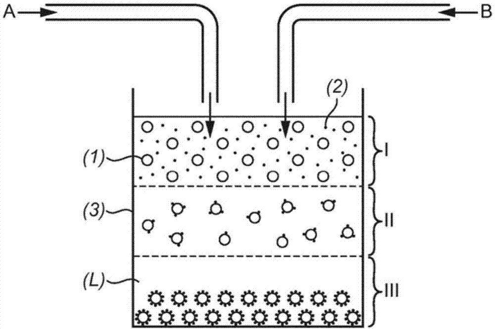
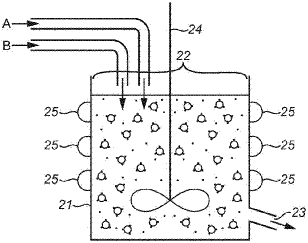
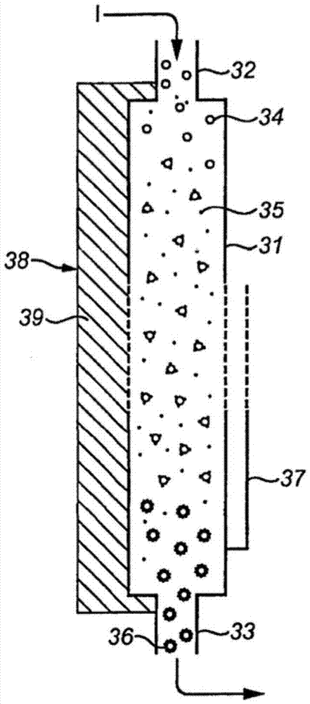
[0225] In the first holding tank, with a D50 value of 9.89μm and 0.977m 2 Silicon particles (ElkemSilgrainHQ) with a specific surface area of ​​0.0072 kg silicon / kg in a carrier liquid comprising a silver nitrate solution in deionized water with 6.3 mmol / m 2 Silver concentration of silicon. HF (50% by weight) was placed in the second holding tank, and deionized water was placed in the third holding tank. The deionized water and HF were pumped through a mixing type T using a metering pump into a PFA tube with a diameter of 6 mm and a length of 30 meters. The 6mm pipe diameter was increased to 8mm for the next 50m and to 10mm for the next 20m. The tubular reactor is submerged in a water bath which is cooled by a cooling cooling loop. A solution comprising silicon and silver nitrate was pumped into a reaction tube 2 m downstream of the HF / water addition point. The flow rates of deionized water, HF and silicon slurry and cooling bath temperature were adjusted to achieve the fo...

Embodiment 2

[0227] Follow the protocol in Example 1, but use 2 Silver nitrate solution with a silver concentration of silicon instead of 6.3mmol / m 2 Silver nitrate solution of silver concentration.


PUM

PropertyMeasurementUnit
lengthaaaaaaaaaa
diameteraaaaaaaaaa
diameteraaaaaaaaaa

Abstract

The present invention relates to a method of forming a metal coated particle, to metal coated particles prepared according to the method and the use of these metal coated particles. The method comprises the steps of: providing a source of base particles to be coated; providing a source of a metal-comprising coating particles; and feeding the base particles specified in step (a) and the source of metal comprising coating particles specified in step (b) into a continuous reactor including heat exchange means to cause contact of the base particles with the source of coating particles thereby to form the metal coated particles. The coated particles include a homogeneous coating and can be used in a variety of applications.

Description

field of invention [0001] The present invention relates to a method of forming metal-coated (cladding) particles, metal-coated particles prepared according to this method and uses of these metal-coated particles. Background of the invention [0002] Metal-coated materials, including metal-coated particles, are well known to those skilled in the art and have been used in a variety of applications such as corrosion protection, medical implants, and antifouling systems. Metallic coatings have also been used to repair and protect underlying substrates and to modify their thermal and electrical conductivity. Materials including silver or copper coatings are often used in antimicrobial applications. Carbon or carbon-coated silicon nanowires containing metal nanoparticles such as platinum (Pt), ruthenium (Ru), iron (Fe), cobalt have been used as electrodes in fuel cell applications (EP2378597). (Co), gold (Au), chromium (Cr), molybdenum (Mo), tungsten (W), manganese (Mn), technet...

Claims


Application Information

Patent Timeline
Patent Type & Authority Applications(China)
IPC IPC(8): C23C18/16B01J19/18C23C18/08C23C18/42C23C18/54
CPCC23C18/1635C23C18/168C23C18/1676C23C18/08C23C18/1619C23C18/1689C23C18/54B01J2/006C23C18/42Y02E60/10C23C20/04H01M4/134C23C18/1639
Inventor D.W.本特
Owner NEXANS
Learn More