Preparing method and detecting method of liquid grid type grapheme field-effect tube based on polyimide (PI)
A technology of field effect transistors and graphene, which is applied in the direction of transistors, single semiconductor device testing, semiconductor/solid-state device manufacturing, etc., can solve problems such as complex processing technology and stability of flexible substrates, and achieve convenient surface modification and good biological phase. Capacitive and stable performance
- Summary
- Abstract
- Description
- Claims
- Application Information
AI Technical Summary
Problems solved by technology
Method used
Image
Examples
Embodiment 1
[0023] Manufacturing method of graphene field effect tube
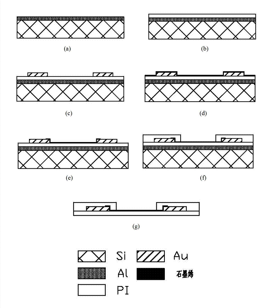
[0024] Device fabrication process such as figure 1 As shown, the details are as follows:
[0025] 1. Clean the silicon wafer with Phiranha solution, rinse it with deionized water, and perform oxygen plasma etching for 5 minutes;
[0026] 2. Deposit 10 nanometers of titanium and 1 microns of aluminum on the surface of the silicon wafer; ( figure 1 a)
[0027] 3. Spin-coat Durimide7510 photoresist on the surface of the aluminum layer, and expose according to the mask; ( figure 1 b)
[0028] 4. Develop and cure PI at 350°C to obtain the device substrate;
[0029] 5. Sputter titanium / gold electrodes on the substrate using the "lift-off" process; ( figure 1 c)
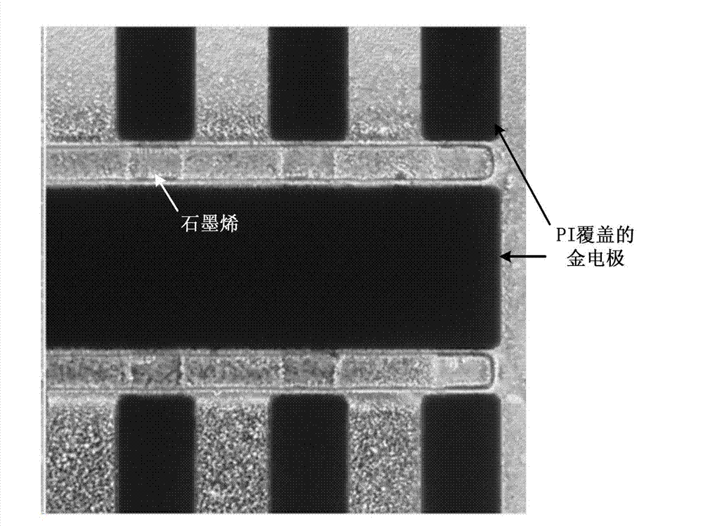
[0030] 6. Copper foil on graphene / PMMA film with FeCl 3 The solution was corroded, and after cleaning with deionized water, the film was transferred to the substrate on which the electrode site had been made, dried at 80°C, and polymethyl methacrylate was d...
Embodiment 2
[0035] Graphene field effect tube performance testing method
[0036] Transfer characteristic curves such as image 3 As shown, the Dirac point appears when the gate voltage is 270mV, and the output characteristic curve is as follows Figure 4 As shown, the test method is as follows:
[0037] 1. Fix the released device on the glass slide, and connect the electrode leads to the ammeter with conductive silver glue;
[0038] 2. Use PDMS to stick a 1 cm high glass ring on the surface of the device to form a cavity, and heat to cure the PDMS;
[0039] 3. Add 1 ml of PBS buffer in the chamber, put the AgCl / Ag reference electrode connected to the voltage source into the chamber;
[0040] 4. Apply a voltage of 100 millivolts between the drain and the source of the FET, and control the magnitude of the drain-source current by controlling the potential of the AgCl / Ag reference electrode to obtain the transfer characteristic curve;
[0041]5. Fix the potential of the AgCl / Ag referenc...
Embodiment 3
[0043] Cell culture and observation on field effect tube
[0044] The culture medium was MEM medium supplemented with 10% fetal bovine serum, 100 μg / ml streptomycin, and 0.11 g / L sodium pyruvate. Routinely cultured SK-N-SH cells were digested with digestive solution (0.25% trypsin, 0.02% EDTA solution), centrifuged, blown, and 4×10 5 cells / mm 3 The density is inoculated on the surface of the field effect tube. The temperature control target was set at 37±0.5°C. After 7 days in culture, cell viability was determined by staining with calcein and with calcein and ethidium homodimer-1. When Calcein stains live cells, the fluorescent signal near the wavelength of 517nm can be detected; when ethidium homodimer-1 stains the dead cells, the fluorescent signal near the wavelength of 617nm can be detected. The fluorescent signal of calcein can be detected by fluorescence microscope (eg Figure 5 shown), no fluorescence signal of ethidium homodimer-1 could be detected, indicating th...
PUM
| Property | Measurement | Unit |
|---|---|---|
| thickness | aaaaa | aaaaa |
| thickness | aaaaa | aaaaa |
| width | aaaaa | aaaaa |
Abstract
Description
Claims
Application Information
 - R&D
- Intellectual Property
- Life Sciences
- Materials
- Tech Scout
- Unparalleled Data Quality
- Higher Quality Content
- 60% Fewer Hallucinations
Browse by: Latest US Patents, China's latest patents, Technical Efficacy Thesaurus, Application Domain, Technology Topic, Popular Technical Reports.
© 2025 PatSnap. All rights reserved.Legal|Privacy policy|Modern Slavery Act Transparency Statement|Sitemap|About US| Contact US: help@patsnap.com


