Crystalline silicon solar cell with high-photoelectric conversion efficiency and manufacturing method thereof
A technology for a solar cell and a manufacturing method, applied in the field of solar energy utilization, can solve the problems of low equipment production efficiency, poor contact, large shadow loss, etc., and achieve the effects of overcoming electrode warpage deformation, reducing shadow loss, and reducing production costs.
- Summary
- Abstract
- Description
- Claims
- Application Information
AI Technical Summary
Problems solved by technology
Method used
Image
Examples
Embodiment 1
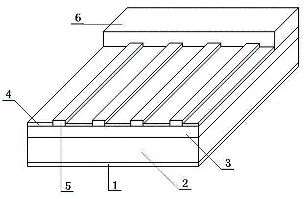
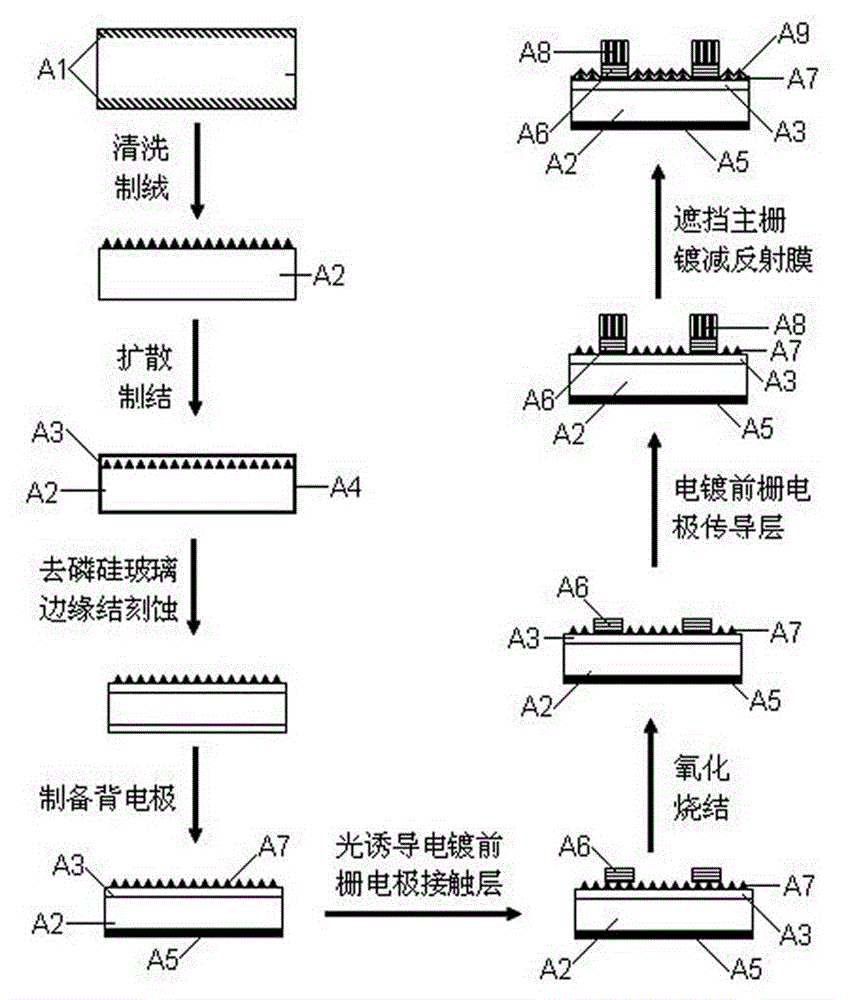
[0037] The prepared 0.01mol / L Co metal ion (CoSO 4 ) The light-induced electroplating electrolyte is injected into the electrolytic cell, and the silicon wafer with the back electrode after texturing, diffusion, etching, dephosphorization, and the back electrode is electrically connected to the electrolytic cell and its control circuit, that is, the back electrode of the silicon wafer and the The Cu counter electrode and the power circuit are well connected, the position of the silicon wafer is fixed and the surface of the N area is kept parallel to the electrolyte surface, and the surface of the N area of the silicon wafer is immersed in the electrolyte. A grid-shaped shading plate is set between the surface of the N-zone of the battery silicon wafer and the fluorescent light source and ensured that it is parallel to the surface of the N-zone, and the light source is activated so that the light passes through the grid-shaped shading plate and irradiates the surface of the N-...
Embodiment 2
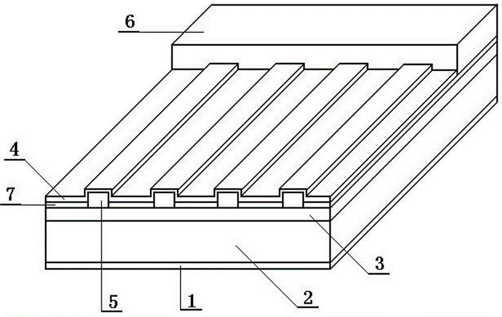
[0039] With 1mol / L Ni metal ion (NiSO 4 ) Electrolyte as light-induced electroplating solution, with Cu electrode as counter electrode, Ag as deposited metal, natural light as light source, prepare the front gate electrode of silicon wafer according to the same process steps as in Example 1, and then place the silicon wafer in oxygen Oxidize and sinter at 780°C for 20 minutes in a nitrogen mixed atmosphere (oxygen flow rate 6L / min, nitrogen flow rate 10L / min), then electroplate a metal Sn conductive layer on the contact layer, and prepare a layer on the surface of the solar cell substrate by physical sputtering TiO 2 The anti-reflection film is processed to obtain the original plate of the crystalline silicon solar cell. After testing, the series resistance is lower than that of batteries prepared in the prior art.
Embodiment 3
[0041] With 0.3mol / L Co metal ion (CoSO 4 ) Electrolyte as light-induced electroplating solution, with Cu electrode as counter electrode, Sn as deposited metal, with LED lamp as light source, prepare the front grid electrode of silicon wafer according to the same process steps as in Example 1, and then place the silicon wafer in Oxidize and sinter at 780°C for 20 minutes in a pure oxygen atmosphere (flow rate 6L / min), then electroplate a metal Ag conductive layer on the contact layer, and prepare a layer of Si on the surface of the solar cell substrate by gel sol method 3 N 4 The anti-reflection film is processed to obtain the original plate of the crystalline silicon solar cell. After testing, the series resistance is lower than that of batteries prepared in the prior art.
PUM
 Abstract
Description
Claims
Application Information
 - R&D Engineer
- R&D Manager
- IP Professional
- Industry Leading Data Capabilities
- Powerful AI technology
- Patent DNA Extraction
Browse by: Latest US Patents, China's latest patents, Technical Efficacy Thesaurus, Application Domain, Technology Topic, Popular Technical Reports.
© 2024 PatSnap. All rights reserved.Legal|Privacy policy|Modern Slavery Act Transparency Statement|Sitemap|About US| Contact US: help@patsnap.com


