
Same-wavelength double-beam narrow-spot laser quick cladding method

A dual-beam, same-wavelength technology, applied in the coating process and coating of metal materials, can solve the problems of easy cracking of the cladding layer, low laser cladding efficiency, and high processing cost, and achieve controllable dilution rate and automation. The effect of high degree and reduction of processing cost

Inactive Publication Date: 2012-04-11
NANCHANG HANGKONG UNIVERSITY
View PDF1 Cites 20 Cited by
  • Summary
  • Abstract
  • Description
  • Claims
  • Application Information

AI Technical Summary

Problems solved by technology

However, so far, laser cladding technology has not been widely used in industry. There are two key reasons: one is that the efficiency of laser cladding is low, which leads to high processing costs; the other is that the cladding layer is prone to cracks. Limit the practical application of this technology

Method used


Image

  • Same-wavelength double-beam narrow-spot laser quick cladding method
  • Same-wavelength double-beam narrow-spot laser quick cladding method

Examples


Embodiment 1

[0020] A Ni-based alloy coating was prepared on the surface of a 70Mn2Mo cast steel hot roll by rapid cladding with a double-beam narrow-spot laser at the same wavelength, and the thickness of the coating was 2 mm.

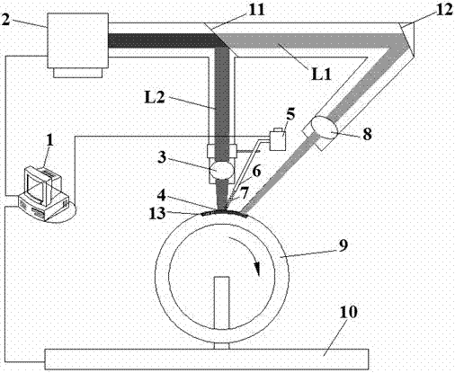
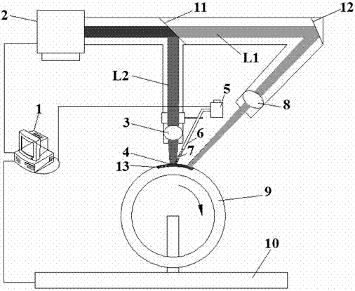
[0021] The implementation process of this embodiment is, as figure 1 shown.

[0022] (1) Use a grinder to derust the surface of the 70Mn2Mo cast steel hot roll 9, then use a mixed solution of sodium hydroxide and sodium carbonate with a volume ratio of 1:1 to degrease, then wash and dry with pure water, Finally, sandblasting;

[0023] (2) The laser beam splitter 11 with a fixed beam splitting ratio is used to split the laser beam emitted by the Nd:YAG laser 2 with a wavelength of 1.06 μm into a laser beam L1 and a laser beam L2, and the laser beam L1 is reflected by the mirror 12 and focused by the focusing mirror 8 After being focused, it acts on the surface of the 70Mn2Mo cast steel hot roll 9, and the laser beam L2 acts on the surface of the 70Mn2Mo cast stee...

Embodiment 2

[0029] WC-12 wt.% Co was clad on the surface of hydraulic cylinder piston rod by rapid cladding method with double-beam narrow-spot laser at the same wavelength. The thickness of the coating was 1.8 mm, and the material of hydraulic cylinder piston rod was No. 35 steel.

[0030] (1) Use a grinding machine to derust the surface of the piston rod 9 of the hydraulic cylinder, then use a mixed solution of steel hydroxide and sodium carbonate with a volume ratio of 1:1 to degrease, then wash and dry with pure water, and finally sandblasting;

[0031](2) The laser beam splitter 11 with a fixed beam splitting ratio is used to split the laser beam emitted by the Nd:YAG laser 2 with a wavelength of 1.06 μm into a laser beam L1 and a laser beam L2, and the laser beam L1 is reflected by the mirror 12 and focused by the focusing mirror 8 After being focused, it acts on the surface of the piston rod 9 of the hydraulic cylinder, and the laser beam L2 acts on the surface of the piston rod 9 ...


PUM

PropertyMeasurementUnit
wavelengthaaaaaaaaaa
thicknessaaaaaaaaaa
thicknessaaaaaaaaaa

Abstract

The invention discloses a same-wavelength double-beam narrow-spot laser quick cladding method, which is characterized by comprising the following steps of: (1) performing rust removing, oil removing, cleaning and sand blasting treatment on the surface of a substrate; (2) splitting a laser beam of the same wavelength into two beams of laser by using a laser beam splitter mirror; (3) applying a first beam of laser to the surface of the substrate for performing preheating treatment on the substrate; (4) blowing alloy powder into a molten pool formed on a second beam of laser on the surface of the substrate by using a powder nozzle of an automatic powder feeder; (5) moving a numerically-controlled machine too along the vertical direction of a laser scanning speed by 40-80 percent of the diameter of a laser spot; and (6) repeating the steps (2)-(5) till the thickness of a coating reaches a required thickness, or ending work. The method has the advantages: (1) the processing cost is reduced greatly; (2) the substrate has a small heat affected zone, and is not deformed; and (3) the shape and size of the substrate are unlimited.

Description

technical field [0001] The invention relates to a method for rapid cladding of narrow-spot lasers with double beams of the same wavelength, and belongs to the technical field of laser processing. Background technique [0002] Important damages such as corrosion, wear and fatigue fracture of metal parts, the damage and economic losses caused are very alarming. For example, the loss caused by corrosion in the United States in 1995 reached 300 billion U.S. dollars, and the economic loss caused by friction and wear in my country every year up to 100 billion yuan. Therefore, using methods such as surface modification and coating to improve the surface properties of metal parts, repair, control or prevent surface damage can prolong their service life and obtain huge economic benefits. [0003] Conventional surface coating methods include electroplating, thermal spraying, surfacing and laser cladding. Among them, electroplating has the advantages of simple process, low operation m...

Claims


Application Information

Patent Timeline
Patent Type & Authority Applications(China)
IPC IPC(8): C23C24/10
Inventor 周圣丰戴晓琴
Owner NANCHANG HANGKONG UNIVERSITY
Learn More