
X-ray tube anode arrangement

a technology of anodes and x-ray tubes, which is applied in the direction of x-ray tube cooling convertors, x-ray tube targets, etc., can solve the problems of high temperature cannot be avoided, the anode environment in the x-ray tube is very harsh, and the x-ray intensities are also very high, so as to achieve excellent reliability and high power operation

Active Publication Date: 2018-03-06
PANALYTICAL BV
View PDF7 Cites 1 Cited by
  • Summary
  • Abstract
  • Description
  • Claims
  • Application Information

AI Technical Summary

Benefits of technology

The solution provides an X-ray anode arrangement that withstands high temperatures, temperature gradients, radiation, and electric fields, significantly improving tube reliability and power switch tolerance compared to conventional setups.

Problems solved by technology

As the power of the X-ray tube rises, high temperatures cannot be avoided.
Thus, the environment of the anode in an X-ray tube can be very harsh-temperatures can be high and x-ray intensities also very high.
However, such materials can have thermal expansion mismatches with the anode material which can lead to high stresses.
Selection of alternative materials is not easy, since it is not sufficient to simply choose another heat spreader material.

Method used


Image

  • X-ray tube anode arrangement
  • X-ray tube anode arrangement
  • X-ray tube anode arrangement

Examples


Embodiment Construction

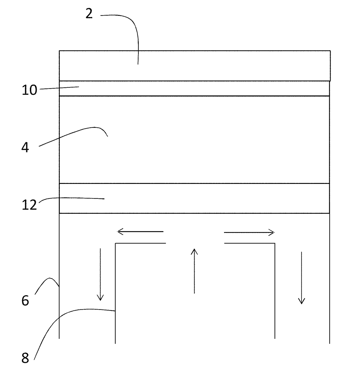
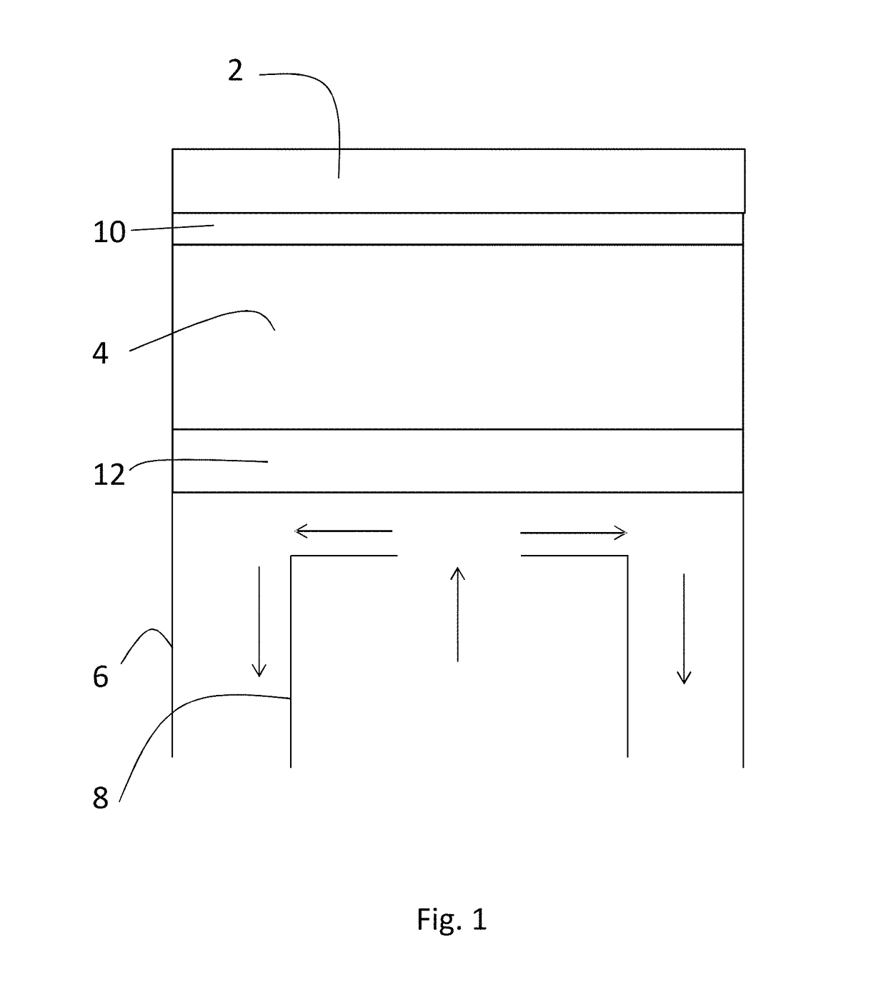
[0031]Referring to FIG. 1, an X-ray tube anode arrangement includes anode 2 is made of rhodium mounted on a heat spreader 4. On the rear of the heat spreader there is provided a cooling arrangement 6,8.

[0032]The heat spreader 4 is made of an alloy of molybdenum and copper, having an alloy composition chosen so that the thermal expansion coefficient matches the thermal expansion coefficient of rhodium.

[0033]The inventors have tested a number of different approaches to fixing the anode to the heat spreader. Good results have been obtained using a diffusion bond of gold. Thus, a bonding layer of joint material 10, in this case of gold, is provided between the anode 2 and the heat spreader 4 to firmly fix the anode to the heat spreader.

[0034]The layer of joint material may have a thickness of 5 to 200 μm, in embodiments 10 to 100 μm for example 50 μm.

[0035]A layer of corrosion resistant material 12 is provided on the rear of the heat spreader to avoid corrosion of the heat spreader 4. T...


PUM

PropertyMeasurementUnit
thicknessaaaaaaaaaa
temperatureaaaaaaaaaa
thicknessaaaaaaaaaa

Abstract

A method of manufacturing an X-ray tube component, includes diffusion bonding or brazing an anode of rhodium, molybdenum or tungsten to a heat spreader of molybdenum, tungsten, or a composite of molybdenum and / or tungsten. Suitable joint materials for diffusion bonding include gold; suitable joint materials for brazing include an alloy of silver and copper, an alloy of silver, copper and palladium, an alloy of gold and copper or an alloy of gold, copper and nickel. The resulting tube component delivers reliable behaviors and the joint can withstand high temperatures, high temperature gradients, fast temperature changes, extremely high radiation and extremely high electric field, while maintaining good high vacuum properties.

Description

CROSS-REFERENCE TO RELATED APPLICATIONS[0001]The present application claims priority under 35 U.S.C. § 119 to European Patent Application No. 15150816.5, filed Jan. 12, 2015, which is hereby incorporated by reference in its entirety.FIELD OF INVENTION[0002]The invention relates to a method of making an X-ray tube anode arrangement, the resulting anode arrangement and an X-ray tube including such an anode arrangement.BACKGROUND TO THE INVENTION[0003]X-ray tubes include an anode. High energy electrons impact the anode driven by a voltage drop between the anode and a cathode. A small part of the energy of the high energy electrons is converted into X-rays. The rest of the energy must be removed by cooling.[0004]This cooling may be carried out using a heat spreader. The overall heat transfer coefficient is important. Therefore, heat spreader materials with a high thermal conductivity are necessary to keep the anode temperature as low as possible. As the power of the X-ray tube rises, hi...

Claims


Application Information

Patent Timeline
Patent Type & Authority Patents(United States)
IPC IPC(8): H01J35/18H01J35/12H01J9/14H01J35/08
CPCH01J35/08H01J9/14H01J35/12H01J2235/1262H01J2235/084H01J2235/1204
Inventor VAN DER BORST, J.FILMER, BARTHAGELUKEN, BENSCHALLEY, JOSMIHALCA, ROMULUS
Owner PANALYTICAL BV
Learn More