
Dielectric ceramics, and laminated ceramic capacitor

a technology of laminated ceramic and dielectric ceramic, which is applied in the direction of ceramics, fixed capacitor electrodes, fixed capacitors, etc., can solve the problems of deterioration in reliability, increase the possibility of occurrence of defective articles, and decrease in dielectric, so as to improve the ac voltage characteristics of capacitance, improve the ac voltage characteristics, and improve the effect of ac voltage characteristics

Active Publication Date: 2011-03-22
MURATA MFG CO LTD
View PDF11 Cites 12 Cited by
  • Summary
  • Abstract
  • Description
  • Claims
  • Application Information

AI Technical Summary

Benefits of technology

In the dielectric ceramic of the present invention where the Ni is solid-solved in the crystal grains uniformly or substantially uniformly, and the average solid-solution region of the rare earth element R in the crystal grains is 10% or less (including 0%) in terms of the cross section ratio, the rare earth element R is prevented from being solid-solved in the crystal grains as a consequence of the Ni being solid-solved in the crystal grains uniformly or substantially uniformly, so that the AC voltage characteristics of capacitance can be improved.
Also, since the composition is represented by a general formula: 100AmBO3+aNiO+bROn+cMOv+dMgO+eXOw, and the m, a, b, c, d and e satisfy 0.96≦m≦1.030, 0.05≦a≦3, 0.1≦b≦1.5, 0.1≦c≦1.0, 0.1≦d≦1.5, and 0.05≦e≦3.5, respectively, it is possible to obtain a dielectric ceramic having improved AC voltage characteristics while any of various characteristics such as dielectric characteristics, temperature characteristics, withstand voltage, reliability and the like are not impaired.
Even when a part of the Ba is replaced by at least one of Sr and Ca, and a part of the Ti is replaced by at least one of Zr and Hf, the aforementioned effect can be achieved.
Also, in the laminated ceramic capacitor of the present invention having a ceramic sintered body made up of a dielectric layers and an internal electrodes alternately stacked, external electrodes being formed on ends of the ceramic sintered body, and the external electrodes being electrically connected with the internal electrodes, the dielectric layer is formed of the dielectric ceramic, so that it is possible to obtain a laminated ceramic capacitor having a stable capacitance with respect to changes in AC voltage, capable of keeping a desired large dielectric constant and excellent temperature characteristics, having small dielectric loss and excellent withstand voltage, and capable of ensuring reliability.
Concretely, it is possible to obtain a laminated ceramic capacitor having a percentage change in capacitance by voltage at an effective voltage 0.1 Vrms relative to the effective voltage at 0.5 Vrms of within ±8%, a dielectric constant ∈ of 2800 or more, a percentage of change in capacitance at −55° C. to +105° C., based on capacitance at 25° C., of within ±22%, satisfying X6S characteristics of EIA standard, having an insulation breakage voltage of 100V or more, and excellent reliability as evidenced by no occurrence of defective article after a continuous operation at high temperature.
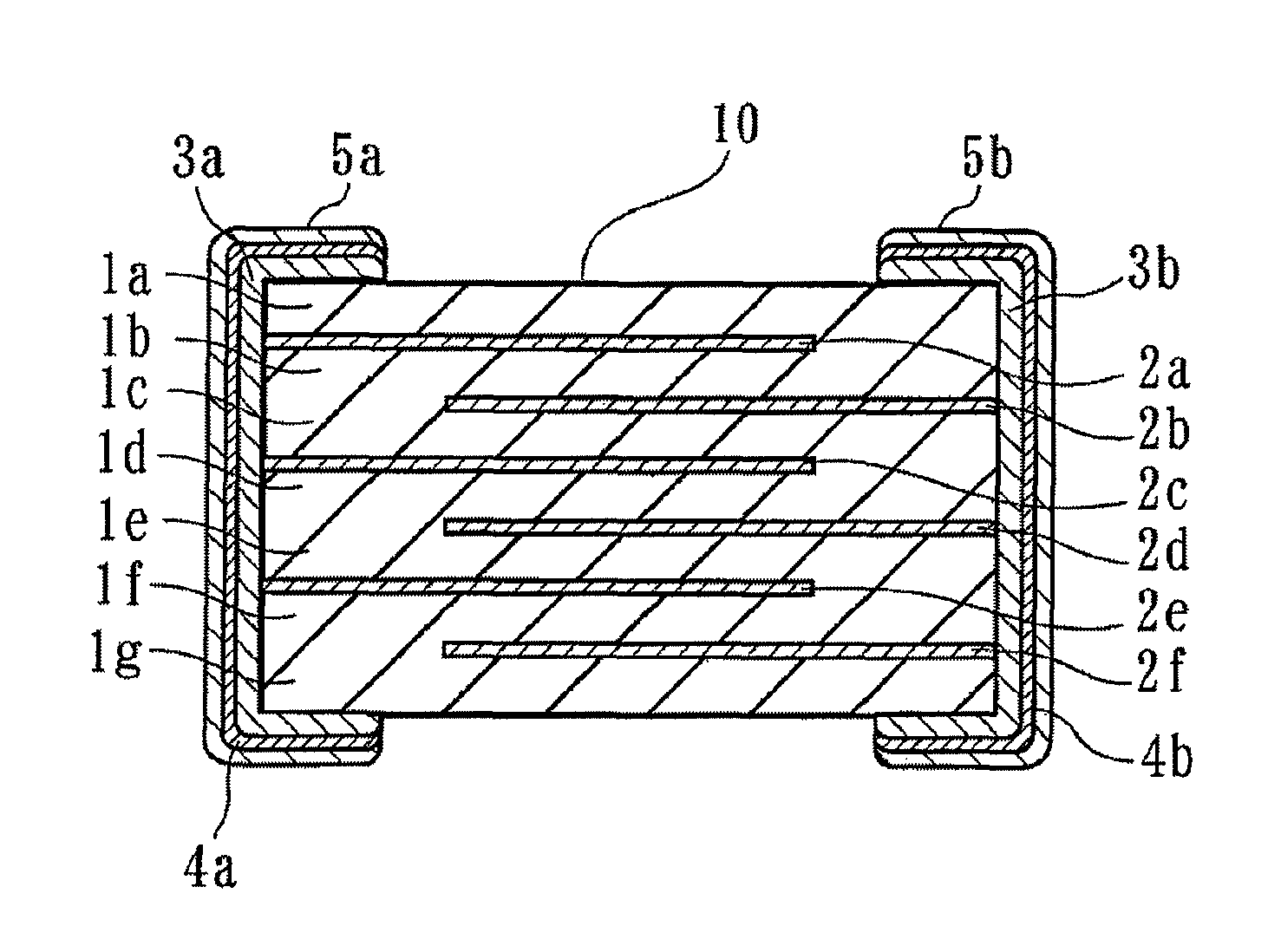
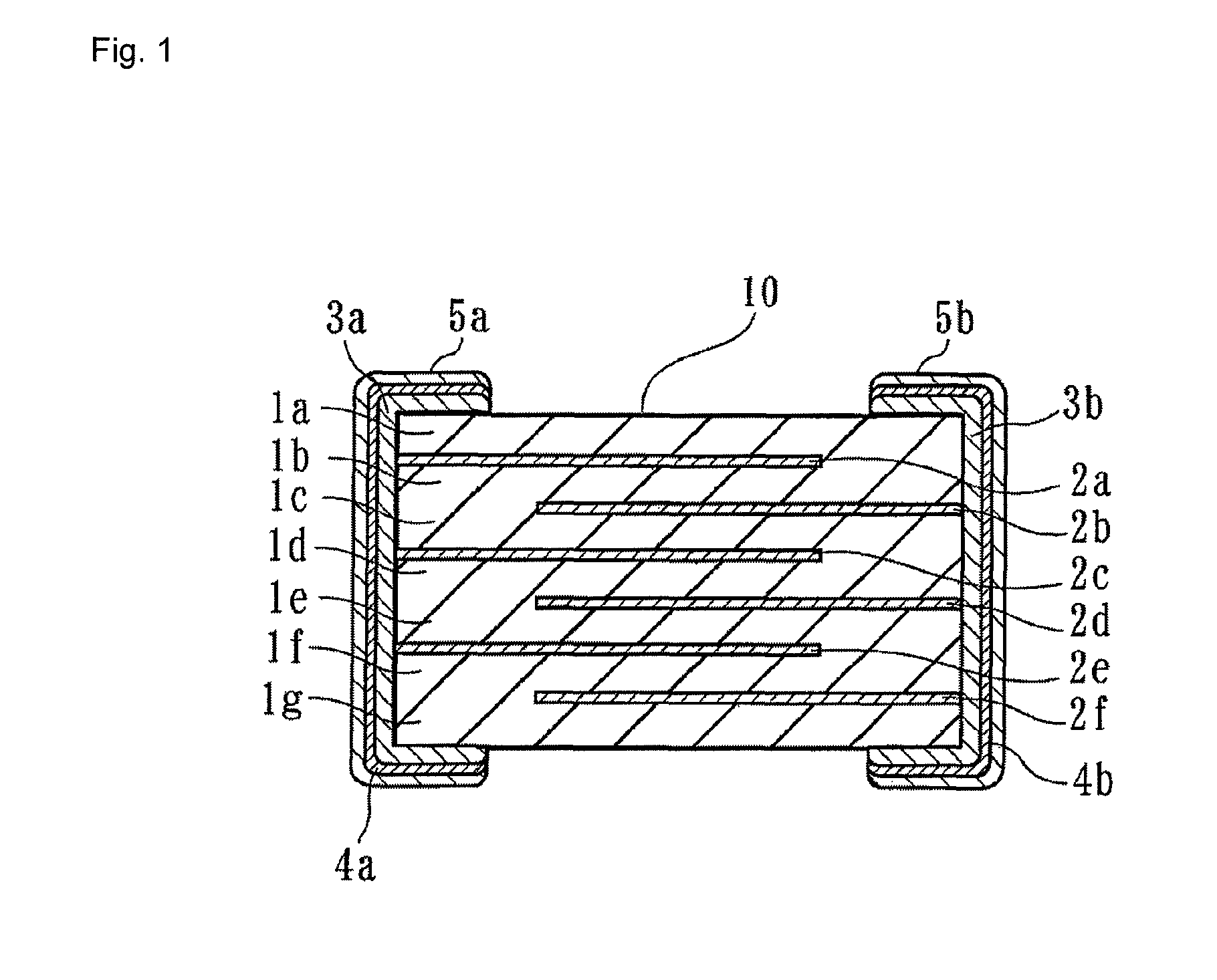
FIG. 1 is a section view showing one embodiment of a laminated ceramic capacitor produced by using a dielectric ceramic of the present invention.

Problems solved by technology

However, when the dielectric layer is thinned, a high field voltage intensity is applied to the dielectric layer, so that a decrease in dielectric constant or a deterioration in temperature characteristics may be caused, or the insulation resistance may decrease as a result of long-time driving at a high temperature, to increase the possibility of occurrence of defective articles.
This may result in deterioration in reliability.

Method used


Image

  • Dielectric ceramics, and laminated ceramic capacitor
  • Dielectric ceramics, and laminated ceramic capacitor

Examples


example 1

Preparation of Sample

Sample No. 1

As ceramic base materials, BaCO3, TiO2, and NiO were prepared, and these ceramic base materials were weighed so that the blending ratio m between Ba and Ti was 1.010, and the molar part a of NiO relative to 100 parts by mol of BaTiO3 was 1.0.

Next, these weighed materials were put into a ball mill together with PSZ balls and pure water, wet mixed and ground for 48 hours, and calcined at a temperature of 1100° C. to prepare a calcined powder.

Next, as additive materials, Dy2O3, MnCO3, MgCO3, and SiO2 were prepared. Then these additive materials were weighed so that the dielectric ceramic satisfied the following general formula (B).

100Ba1.010TiO3+aNiO+1.0DyO3 / 2+0.3MnO+1.0MgO+1.5SiO2

These additive materials were put into a ball mill together with the calcined powder, wet mixed in the ball mill for 24 hours, and then dried by evaporation to obtain a ceramic material powder.

Then, to the ceramic material powder was added a polyvinyl butyral-based binder as ...

example 2

Preparation of Sample

Samples Nos. 11 to 18

A ceramic material powder having the same composition as that in Sample No. 1 was prepared and a ceramic laminate was obtained.

Next, the ceramic laminate was subjected to a binder removing treatment at a temperature of 300° C., and each sample was subjected to a burning treatment which was conducted for about two hours under a reductive atmosphere of H2—N2—H2O gas whose oxygen partial pressure was controlled to 10−9 to 10−12 MPa at different temperatures ranging from 1140 to 1220° C. to obtain laminated ceramic capacitors of Sample Nos. 11 to 18.

Sample Nos. 19 to 26

Laminated ceramic capacitors of Sample Nos. 19 to 26 burnt at different temperatures were obtained in a similar manner and procedure as that in Sample Nos. 11 to 18 except that NiO was not added.

Structural Analysis of Ceramic Texture

For each sample of Sample Nos. 11 to 26, the structure of a ceramic texture was analyzed in a manner similar to Example 1, and the solid-solved state ...

example 3

Preparation of Sample

As ceramic base materials, BaCO3, TiO2, and NiO were prepared, and these ceramic base materials were weighed so that the blending molar ratio m between Ba and Ti and the molar part a of NiO relative to 100 parts by mol of BaTiO3 were the values as shown in Table 5, and a calcined powder was prepared in a similar manner and procedure as in Example 1.

Next, as additive materials, R oxides containing a rare earth element R (La2O3, CeO2, Pr6O11, Nd2O3, Sm2O3, Eu2O3, Gd2O3, Tb2O3, Dy2O3, Ho2O3, Er2O3, Tm2O3, Yb2O3, Lu2O3, Y2O3), M oxides containing a metal element M (MnO, Fe2O3, CuO, CoO, V2O5, WO3, Cr2O3, MoO2, Al2O3), MgO, and SiO2 were prepared.

Then these additive materials were weighed so that b, c, d and e in the following general formula (C) of the dielectric ceramic satisfied the values shown in Table 5.

100BamTiO3+aNiO+bROn+cMOv+dMgO+eSiO2

Next, these additive materials were mixed with the calcined powder in a ball mill, and then dried by evaporation, to obtain...


PUM

PropertyMeasurementUnit
AC voltageaaaaaaaaaa
dielectric constantaaaaaaaaaa

Abstract

A dielectric ceramic contains a BaTiO3-based compound as a main ingredient, and can be represented by the general formula: 100AmBO3+aNiO+bROn+cMOv+dMgO+eXOw where R represents a rare earth element such as Dy, M represents a metal element such as Mn, and X represents a sintering aid component containing Si. Ni is uniformly solid-solved in crystal grains, and the solid-solution region of the rare earth element in the crystal grains is an average 10% or less in terms of a cross section ratio. 0.96≦m≦1.030, 0.05≦a≦3, 0.1≦b≦1.5, 0.1≦c≦1.0, 0.1≦d≦1.5, and 0.05≦e≦3.5 are satisfied. A laminated ceramic capacitor has dielectric layers formed of the dielectric ceramic. As a result, a dielectric ceramic, and a laminated ceramic capacitor having excellent AC voltage characteristics, capable of keeping desired dielectric characteristics and excellent temperature characteristics, and having excellent withstand voltage and capable of ensuring reliability can be realized.

Description

TECHNICAL FIELDThe present invention relates to a dielectric ceramic and a laminated ceramic capacitor, and more specifically, to a dielectric ceramic suited as a dielectric material of a laminated ceramic capacitor of small size and large capacity, and a laminated ceramic capacitor produced by using the dielectric ceramic.BACKGROUND ARTA laminated ceramic capacitor is an electronic component that is used in the circuits of a wide variety of electronic devices, and downsizing of a laminated ceramic capacitor is necessary as such an electronic device is downsized.Such a type of the laminated ceramic capacitor is formed by laminating dielectric layers interposed by internal electrodes, and sintering the laminate. For achieving downsizing of the laminated ceramic capacitor without causing reduction in its capacity, it is necessary to thin the dielectric layer.However, when the dielectric layer is thinned, a high field voltage intensity is applied to the dielectric layer, so that a decr...

Claims


Application Information

Patent Timeline
Patent Type & Authority Patents(United States)
IPC IPC(8): H01G4/06C04B35/00
CPCC04B35/4682C04B35/49C04B35/6262C04B35/62665C04B35/62685H01B3/12H01G4/1227H01G4/30C04B2235/3201C04B2235/3203C04B2235/3206C04B2235/3208C04B2235/3213C04B2235/3217C04B2235/3224C04B2235/3225C04B2235/3227C04B2235/3229C04B2235/3239C04B2235/3241C04B2235/3244C04B2235/3256C04B2235/3258C04B2235/3262C04B2235/3272C04B2235/3275C04B2235/3279C04B2235/3281C04B2235/3284C04B2235/3289C04B2235/3291C04B2235/3409C04B2235/3418C04B2235/656C04B2235/6582C04B2235/6584C04B2235/6588C04B2235/79
Inventor SASABAYASHI, TAKEHISANAKAMURA, TOMOYUKIISHIHARA, MASAYUKIYAO, TAKAYUKI
Owner MURATA MFG CO LTD
Learn More