Membrane electrode assembly and fuel cell

a membrane electrode and fuel cell technology, applied in cell components, electrochemical generators, impregnation manufacturing, etc., can solve the problems of insufficient security of water exhaustion paths insufficient water exhaustion properties and insufficient gas diffusivity in gas diffusion layers, etc., to achieve the effect of improving voltage characteristics

Inactive Publication Date: 2015-02-10
JX NIPPON OIL & ENERGY CORP
View PDF16 Cites 0 Cited by
  • Summary
  • Abstract
  • Description
  • Claims
  • Application Information

AI Technical Summary

Benefits of technology

[0014]The present invention is made in view of such circumstances, and an object is to provide a fuel cell capable of simultaneously satisfying water exhaustion property and gas diffusivity and improving a voltage characteristic.
[0016]According to the above aspect of the present invention, since the strike-through of the microporous layer of the gas diffusion layer is performed so as to reach the other surface of the gas diffusion substrate, the water generated through the electrochemical reaction can be exhausted to the separator side by using the strike-through portion in the microporous layer as a center. It is considered that the carbon in the microporous layer constitutes a carbon path, so that the generated water exhaustion is effectively performed. In addition, the strike-through ratio of the microporous layer is a predetermined ratio, so that it is possible to simultaneously satisfy the generated water exhaustion and the gas diffusivity while the gas diffusivity of the gas diffusion layer is maintained. In addition, the strike-through region is formed in a dotted form, so that the generated water exhaustion can be uniformly performed over the entire gas diffusion layer, so that it is possible to further improve the generated water exhaustion property. Accordingly, it is possible to improve the voltage characteristic of the fuel cell.
[0017]In the above aspect of the present invention, in the membrane electrode assembly, the strike-through ratio may be in a range of 0.3% to 3.9%. According to the above aspect of the present invention, it is possible to further improve the exhaustion property of the gas diffusion layer and the voltage characteristic of the fuel cell.
[0018]In the above aspect of the present invention, in the membrane electrode assembly, the strike-through ratio may be in a range of 0.4% to 3.1%. According to the above aspect of the present invention, it is possible to further improve the exhaustion property of the gas diffusion layer and the voltage characteristic of the fuel cell.
[0019]According to another aspect of the present invention, there is provided a fuel cell. The fuel cell includes the membrane electrode assembly according to the above aspect of the present invention. According to the above aspect of the present invention, it is possible to improve the exhaustion property of the gas diffusion layer and the voltage characteristic of the fuel cell.
[0021]According to a fuel cell of the present invention, it is possible to improve a voltage characteristic.

Problems solved by technology

However, in a fuel cell in the related art, water exhaustion path in a gas diffusion layer is not sufficiently secured, and the water exhaustion property and the gas diffusivity in the gas diffusion layer are not simultaneously satisfied.

Method used


Image

  • Membrane electrode assembly and fuel cell
  • Membrane electrode assembly and fuel cell
  • Membrane electrode assembly and fuel cell

Examples


embodiment

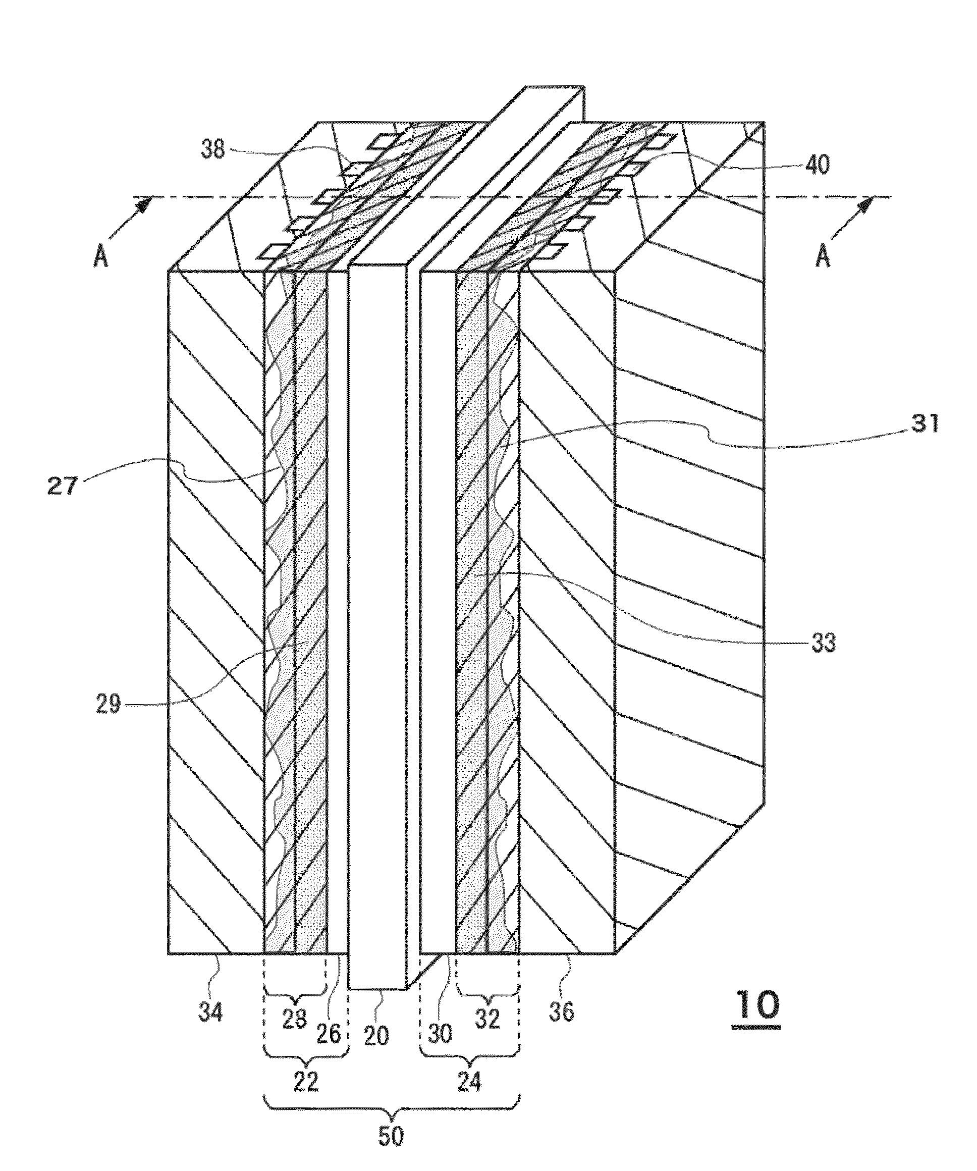
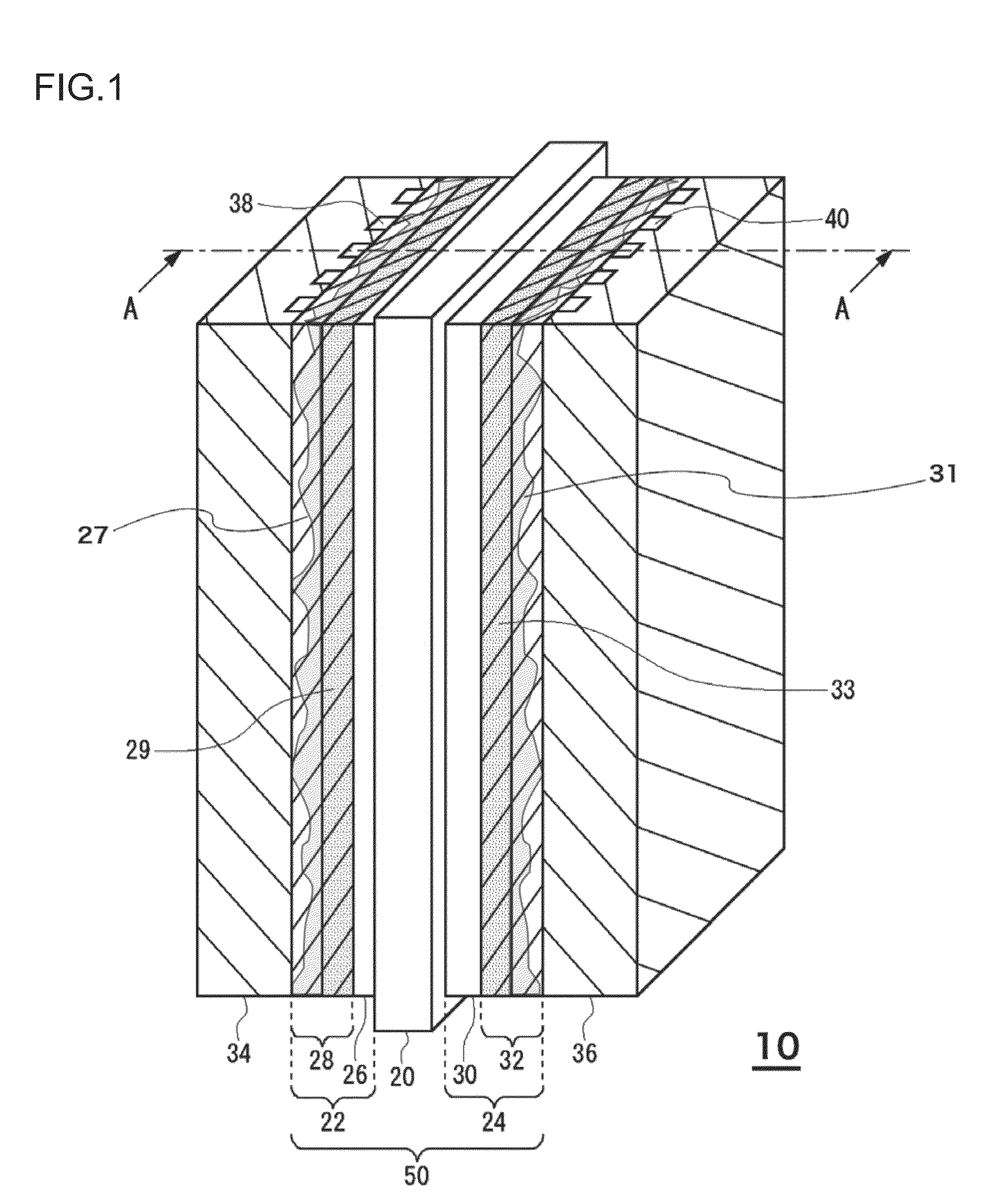
[0029]FIG. 1 is a perspective view schematically illustrating a structure of a fuel cell 10 according to a first embodiment. FIG. 2 is a cross-sectional view taken along line A-A of FIG. 1. The fuel cell 10 includes a plate-shaped membrane electrode assembly 50, and a separator 34 and a separator 36 are installed at two sides of the membrane electrode assembly 50. In this example, although only one membrane electrode assembly 50 is illustrated, a fuel cell stack may be configured by stacking a plurality of membrane electrode assemblies 50 through the separators 34 or the separators 36. The membrane electrode assembly 50 includes a solid polymer electrolyte membrane 20, an anode 22, and a cathode 24.

[0030]The anode 22 includes a stack structure configured with a catalyst layer 26 and a gas diffusion layer 28. On the other hand, the cathode 24 includes a stack structure configured with a catalyst layer 30 and a gas diffusion layer 32. The catalyst layer 26 of the anode 22 and the cata...

example

[0061]In the case where the strike-through ratio of the microporous layer on the rear surface (second surface) of the gas diffusion layer is allowed to be changed, the corresponding change in the generated voltage (voltage characteristic) is analyzed. The membrane electrode assembly in the fuel cell is manufactured according to the following manufacturing method.

(Manufacturing Method)

[0062]A carbon paper (TGP-H-060, manufactured by Toray Industries, Inc.) which becomes a base material of a cathode gas diffusion layer is prepared. The carbon paper is immersed into an FEP dispersion solution so that the weight ratio becomes carbon paper:FEP (tetrafluoro ethylene-hexafluoro propylene copolymer)=95:5 (for cathode), 60:40 (for anode). Next, drying is performed at a temperature of 60° C. for one hour, and after that, thermal treatment (FEP water repelling process) is performed at a temperature of 380° C. for 15 minutes. Therefore, the water repelling process is almost uniformly performed ...


PUM

PropertyMeasurementUnit
temperatureaaaaaaaaaa
thicknessaaaaaaaaaa
thicknessaaaaaaaaaa

Abstract

There is provided a membrane electrode assembly including an anode gas diffusion layer included in an anode and a cathode gas diffusion layer included in a cathode, wherein the anode gas diffusion layer includes an anode gas diffusion substrate and an anode microporous layer disposed on a first surface of the anode gas diffusion substrate, wherein the cathode gas diffusion layer includes a cathode gas diffusion substrate and a cathode microporous layer disposed on a first surface of the cathode gas diffusion substrate, and wherein at least one of a strike-through ratio on a second surface of the anode gas diffusion substrate and a strike-through ratio on a second surface of the cathode gas diffusion substrate is larger than 0.2%.

Description

CROSS-REFERENCE TO RELATED APPLICATIONS[0001]This application is a continuation of International Application No. PCT / JP2011 / 001856, whose international filing date is Mar. 29, 2011 which in turn claims the benefit of Japanese Patent Application No. 2010-084587, filed on Mar. 31, 2010, the disclosures of which Applications are incorporated by reference herein.BACKGROUND OF THE INVENTION[0002]1. Field of the Invention[0003]The present invention relates to a fuel cell which generates electricity through an electrochemical reaction of hydrogen and oxygen.[0004]2. Description of the Related Art[0005]Recently, fuel cells having high energy conversion efficiency and generating no toxic substances through an electricity generation reaction have attracted attention. As one of the fuel cells, there has been known a solid polymer type fuel cell which is allowed to operate at a low temperature of 100° C. or less.[0006]The solid polymer type fuel cell is a device having a basic structure where a...

Claims


Application Information

Patent Timeline
Patent Type & Authority Patents(United States)
IPC IPC(8): H01M8/10H01M4/04H01M4/86H01M4/92H01M4/96H01M8/02
CPCH01M4/86H01M8/1004H01M8/10H01M8/02H01M4/0416H01M4/96H01M4/92Y02E60/521H01M4/8807H01M4/8835H01M8/0234H01M8/0239H01M8/0243H01M8/0245H01M8/04156H01M2008/1095Y02E60/50Y02E60/10
Inventor TAKAMI, HIROFUMISAKAMOTO, SHIGERU
Owner JX NIPPON OIL & ENERGY CORP
Why Eureka
Try Eureka