
Methods and systems for providing illumination of a specimen for a process performed on the specimen

a technology of specimen illumination and process, applied in photomechanical equipment, instruments, nuclear engineering, etc., can solve the problems of power limit, high brightness limit of intensity discharge arc lamps, rapid erosion of electrodes, etc., to reduce the volume of plasma, increase the propagation of generated light, and increase plasma isolation

Active Publication Date: 2010-04-27
KLA TENCOR TECH CORP
View PDF20 Cites 197 Cited by
  • Summary
  • Abstract
  • Description
  • Claims
  • Application Information

AI Technical Summary

Benefits of technology

[0039]In one embodiment, the system includes a gas flow subsystem configured to direct a gas to the plasma such that the gas directed to the plasma affects a shape of the plasma. In another embodiment, the system includes a gas flow subsystem configured to direct a gas to the plasma such that the gas directed to the plasma increases isolation of the plasma. In an additional embodiment, the system includes a gas flow subsystem configured to direct a gas to the plasma at a direction substantially opposite to a direction at which the focusing optics focus the excitation light to the plasma. In a further embodiment, the system includes a gas flow subsystem configured to direct a gas to the plasma at a direction substantially perpendicular to a direction at which the focusing optics focus the excitation light to the plasma. In some embodiments, the system includes a gas flow subsystem configured to direct a gas to the plasma such that the gas increases propagation of the generated light through the plasma.
[0040]In one embodiment, the system includes a gas flow subsystem configured to direct a gas to the plasma through an aperture in an optical element of the focusing optics. In another embodiment, the system includes a gas flow subsystem configured to direct a gas to the plasma through a sonic or supersonic nozzle to reduce a volume of the plasma and to reduce absorption of the generated light by the gas.
[0041]In some embodiments, the system includes a gas flow subsystem configured to direct a gas to the plasma. In one such embodiment, the gas flow subsystem includes a cylindrical-shaped nozzle. In another such embodiment, the gas directed to the plasma increases uniformity of a density profile of the plasma. In an additional such embodiment, the gas directed to the plasma creates an interaction media having a density suitable for interactions between the excitation light and the plasma. In a further such embodiment, a pressure of the gas directed to the plasma is selected based on one or more predetermined characteristics of the plasma. In yet another such embodiment, the gas flow subsystem includes a nozzle through which the gas is directed to the plasma, and a diameter of the nozzle is selected based on one or more predetermined characteristics of the plasma.

Problems solved by technology

However, these light sources have a number of disadvantages, For instance, electrode based, relatively high intensity discharge arc lamps have brightness limits and power limits due to electrostatic constraints on current density from the electrodes, the limited emissivity of gases as black body emitters, the relatively rapid erosion of electrodes made from refractory materials due to the presence of relatively large current densities at the cathodes, and the inability to control dopants (which can lower the operating temperature of the refractory cathodes) for relatively long periods of time at the required emission current.

Method used


Image

  • Methods and systems for providing illumination of a specimen for a process performed on the specimen
  • Methods and systems for providing illumination of a specimen for a process performed on the specimen
  • Methods and systems for providing illumination of a specimen for a process performed on the specimen

Examples


Embodiment Construction

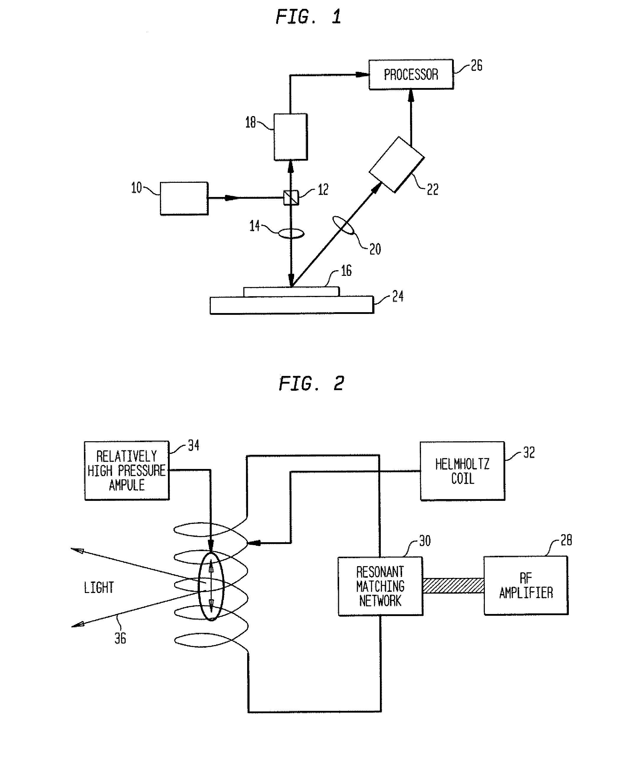
[0082]As used herein, the term “specimen” generally refers to a wafer, a photomask, or a reticle. However, it is to be understood that the methods and systems described herein may be used for providing illumination of any other specimen known in the art and / or determining one or more characteristics (e.g., by inspection, defect review, metrology, imaging, etc.) of any other specimen known in the art.

[0083]As used herein, the term “wafer” generally refers to substrates formed of a semiconductor or non-semiconductor material. Examples of such a semiconductor or non-semiconductor material include, but are not limited to, monocrystalline silicon, gallium arsenide, and indium phosphide. Such substrates may be commonly found and / or processed in semiconductor fabrication facilities.

[0084]A wafer may include one or more layers formed upon a substrate. For example, such layers may include, but are not limited to, a resist, a dielectric material, a semiconductive material, and a conductive ma...


PUM


Abstract

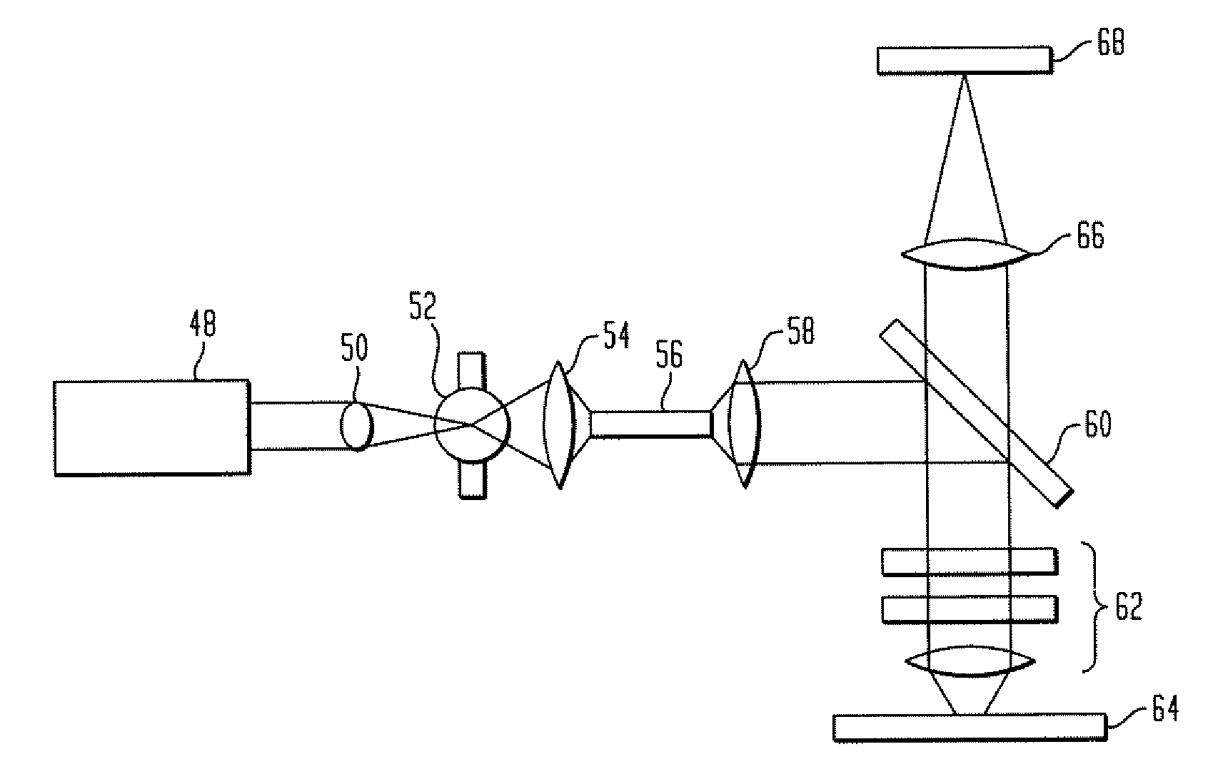
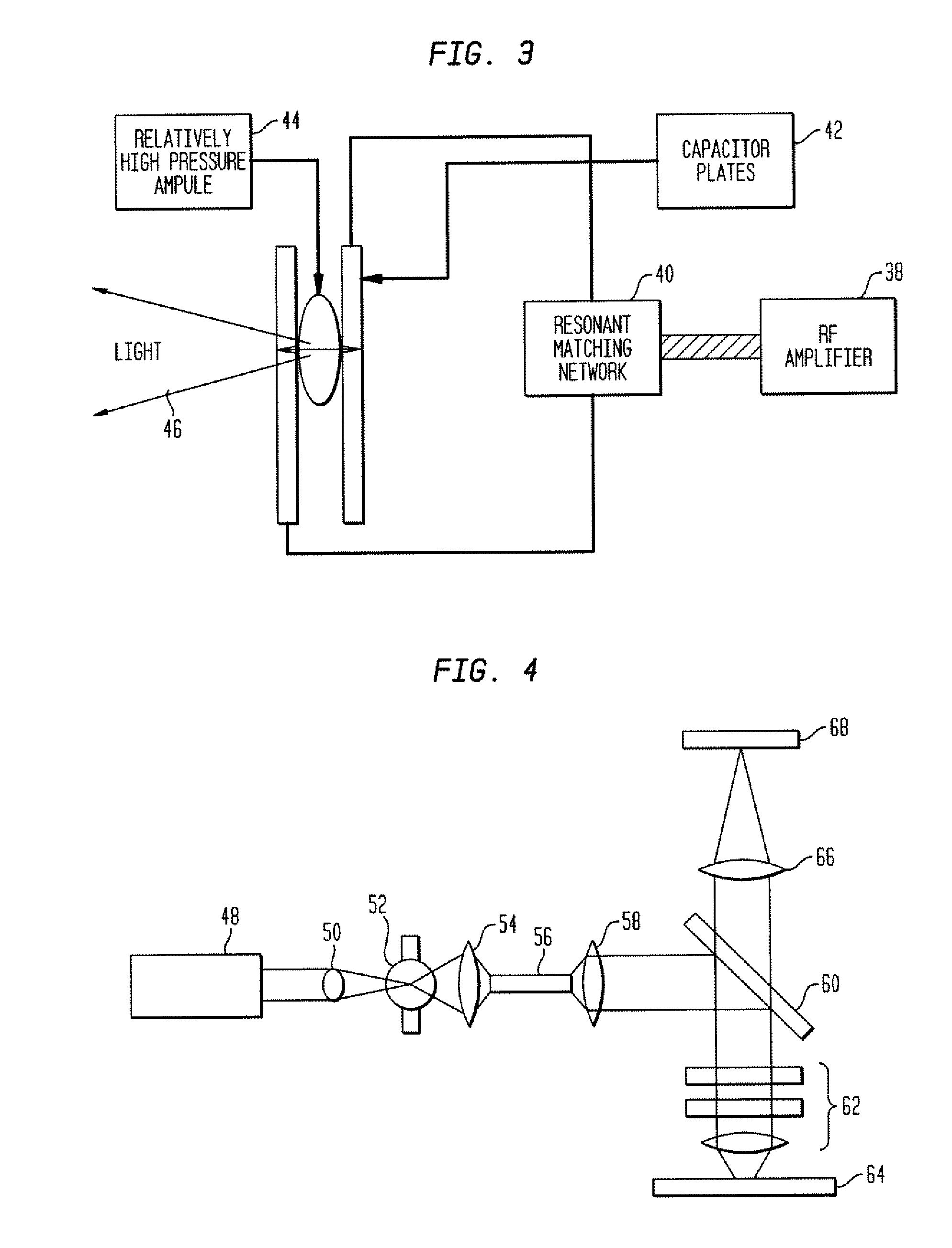
Methods and systems for providing illumination of a specimen for a process performed on the specimen are provided. One system configured to provide illumination of a specimen for a process performed on the specimen includes a laser configured to generate excitation light. The system also includes focusing optics configured to focus the excitation light to a plasma in an electrodeless lamp such that the plasma generates light. The system is also configured such that the light illuminates the specimen during the process.

Description

PRIORITY CLAIM[0001]This application claims priority to U.S. Provisional Application Ser. No. 60 / 806,204 entitled “Methods and Systems for Providing Illumination of a Specimen for Inspection,” filed Jun. 29, 2006, which is incorporated by reference as if fully set forth herein.BACKGROUND OF THE INVENTION[0002]1. Field of the Invention[0003]The present invention generally relates to methods and systems for providing illumination of a specimen for a process performed on the specimen. Certain embodiments relate to methods and systems for providing illumination of a specimen using an electrodeless lamp.[0004]2. Description of the Related Art[0005]The following description and examples are not admitted to be prior art by virtue of their inclusion in this section.[0006]Fabricating semiconductor devices such as logic and memory devices typically includes processing a substrate such as a semiconductor wafer using a large number of semiconductor fabrication processes to form various features...

Claims


Application Information

Patent Timeline
IPC IPC(8): G21G4/00
CPCG01N21/956H01J65/04G03F7/70033G03F7/70575G03F7/70616G01N21/8806G01N21/94G01N21/9501G01N2201/061G01N2021/8825
Inventor KIRK, GREGSOLARZ, RICHKIRK, CHRISDELGADO, GILSCHEMELININ, ANATOLYLI, JIMCHEN, QIBIAOWANG, CHARLES NENGHE
Owner KLA TENCOR TECH CORP
Learn More