
Water vapor passivation of a wall facing a plasma

a plasma wall and water vapor technology, applied in the field of plasma cleaning, can solve the problems of sputter etching, affecting the cleaning effect, and affecting the cleaning effect, and achieve the effect of cleaning porous and soft low-k dielectrics

Inactive Publication Date: 2010-04-13
APPLIED MATERIALS INC
View PDF24 Cites 44 Cited by
  • Summary
  • Abstract
  • Description
  • Claims
  • Application Information

AI Technical Summary

Benefits of technology

The patent describes a method for cleaning and passivating a plasma processing chamber using unexcited water vapor. This is done before igniting a plasma of a processing gas, such as hydrogen, for reducing or etching processes. The method is particularly useful for a plasma pre-cleaning chamber with a remote plasma source. The invention effectively cleans porous and soft low-k dielectrics. The water vapor can be generated from liquid water at room temperature and vacuum pumped to a desired pressure. The same vapor source can also be used to supply water vapor at lower pressure levels.

Problems solved by technology

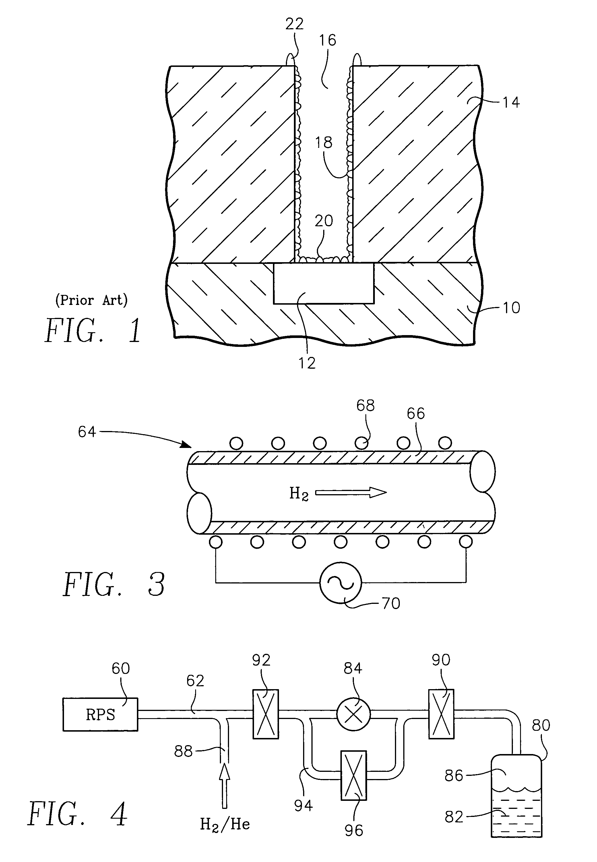
The polymeric coating 18 and the ashing residues 22 interfere with the bonding of the barrier layer to the dielectric layer 14 so that the barrier layer and copper via structure may delaminate during fabrication or during operation, resulting in a substantial reliability problem.
However, low-k dielectric layers tend to be relatively soft.
Therefore, a sputter etch tends to deleteriously etch and degrade the low-k dielectric layer.
However, the in situ oxygen plasma has proved unsatisfactory for the most recent ultra low-k films having a k value of about 2.5 and a porosity of greater than 10%.
However, excited oxygen has not proved satisfactory for the ultra low-k dielectric materials.
Therefore, they are not only very soft, they are also very reactive to an oxidizing dry cleaning.
The hydrogen approach has prevailed, but the results have still not been totally satisfactory.
Although cleaning performance has been observed to be quite good, the expensive remote plasma source has exhibited a short lifetime before it fails.
However, quartz-lined plasma sources even more expensive and quartz has been observed to also degrade in a hydrogen plasma.

Method used


Image

  • Water vapor passivation of a wall facing a plasma
  • Water vapor passivation of a wall facing a plasma
  • Water vapor passivation of a wall facing a plasma

Examples


Embodiment Construction

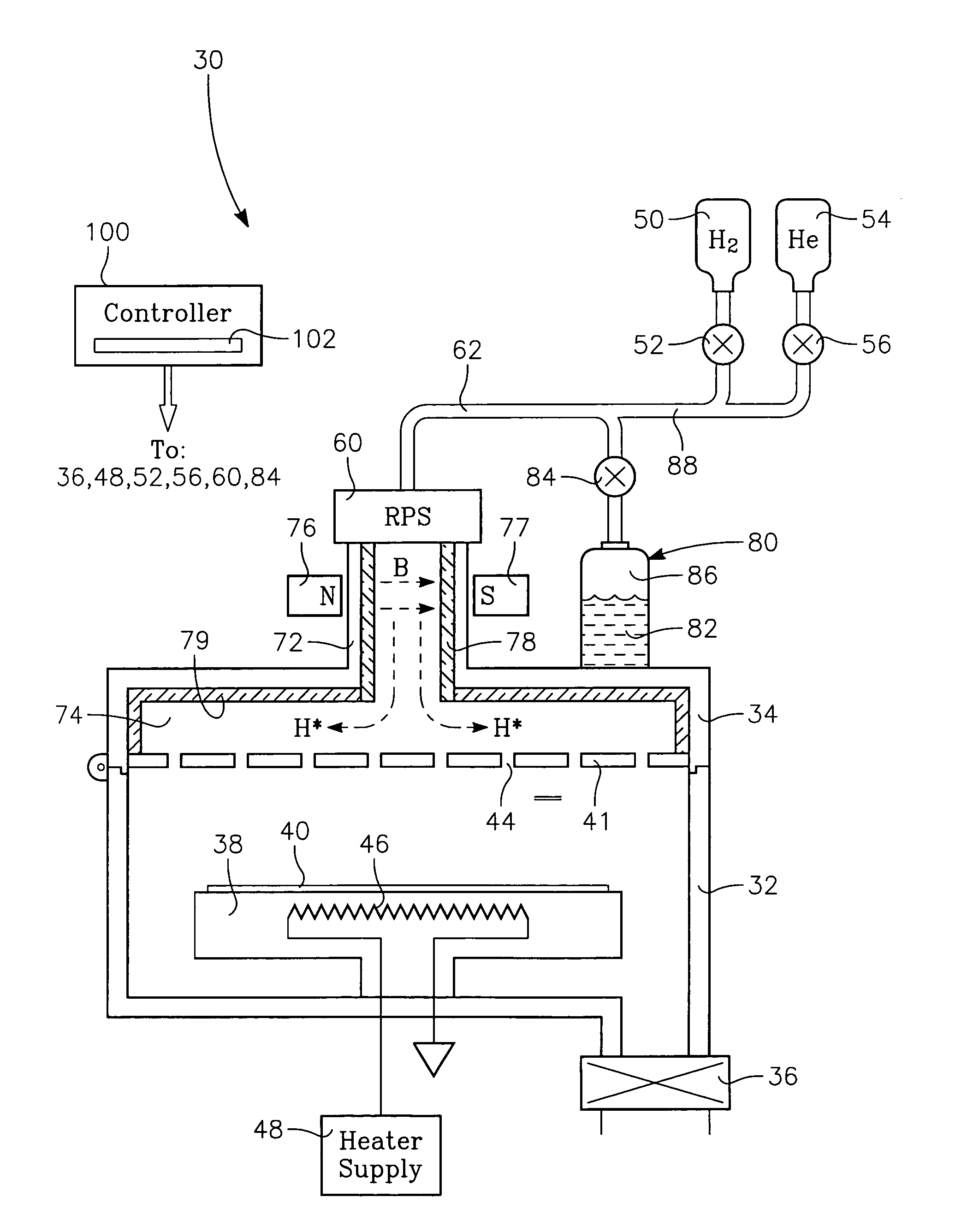
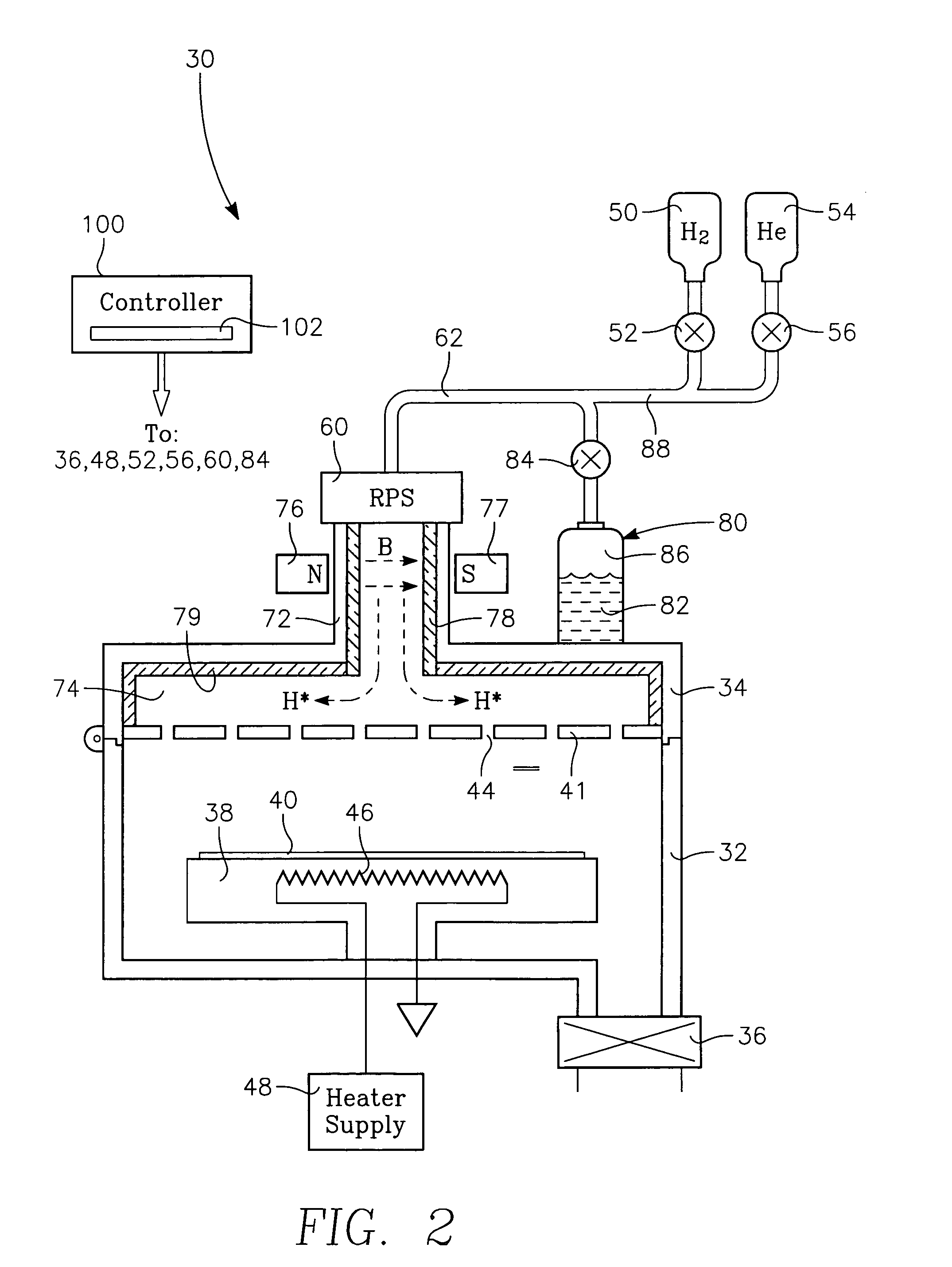
[0018]The hydrogen pre-cleaning process described in the cited patent application Ser. No. 11 / 334,803 advantageously dispenses with the water component of the cleaning plasma so as to avoid degradation of the dielectric constant of the porous low-k dielectric. However, it is now believed that the conventional plasma including water vapor provides some protection to alumina and other dielectric walls. The plasma pre-cleaning process of the cited patent application can be improved by passivating the remote plasma source and other walls facing the plasma with water vapor that has not been excited into a plasma, preferably, prior to ignition of the plasma containing hydrogen but no water.

[0019]A remote plasma cleaning chamber 30 illustrated in the cross-sectional view of FIG. 2 includes a vacuum processing chamber 32 including an lid 34 which may be opened about a hinge and which is pumped by a vacuum pumping system 36. A pedestal 38 within the chamber 32 supports a wafer 40 to be clean...


PUM

PropertyMeasurementUnit
dielectric constantaaaaaaaaaa
dielectric constantsaaaaaaaaaa

Abstract

A chamber passivation method particularly useful for hydrogen plasma cleaning of low-k dielectrics prior to coating a barrier layer into a via hole with hydrogen radicals are provided from a remote plasma source. For each wafer, the chamber is passivated with water vapor (or other gas even more chemabsorbed on plasma facing walls) passed through the remote plasma source prior to the ignition of the hydrogen plasma. The water vapor is absorbed on walls, such as alumina and quartz parts of the remote plasma source, and forms a protective mono-layer that endures sufficiently long to protect the walls during the generation of the hydrogen plasma. Thereby, the plasma facing walls, particularly of a dielectric such as alumina, are protected from etching.

Description

FIELD OF THE INVENTION[0001]The invention relates generally to plasma cleaning in the process of fabricating integrated circuits. In particular, the invention relates to plasma cleaning performed between patterned etching of a dielectric layer and deposition.BACKGROUND ART[0002]Advanced integrated circuits, such as those contemplated for the 45 nm node, will require the use of extra low-k dielectric (electrically insulating) materials for the interlevel dielectric layer interconnecting two levels of wiring. Low-k materials having a dielectric constant of somewhat less than 3.9 (the value for silicon dioxide) have already entered commercial production. However, even lower dielectric constants, for example, below 2.5, will be required in the future. An example of this material is Black Diamond™ II (BDII) dielectric commercially available from Applied Materials of Santa Clara, Calif. This dielectric material, which Li describes in United States Patent Application 2003 / 0194495, may be c...

Claims


Application Information

Patent Timeline
Patent Type & Authority Patents(United States)
IPC IPC(8): B08B7/00
CPCH01L21/76814H01L21/02063C23C16/00
Inventor FU, XINYU
Owner APPLIED MATERIALS INC
Learn More