
Converter control device

a control device and converter technology, applied in the direction of electric variable regulation, process and machine control, instruments, etc., can solve the problems of secondary loss becoming dominant and the loss of primary loss decreasing

Active Publication Date: 2009-12-15
TOYOTA JIDOSHA KK
View PDF13 Cites 11 Cited by
  • Summary
  • Abstract
  • Description
  • Claims
  • Application Information

AI Technical Summary

Benefits of technology

This solution enables reliable and effective feedback control suitable for the number of drive phases, improving voltage conversion efficiency by adapting control gains to match changing load conditions, thereby optimizing energy transfer between power supplies.

Problems solved by technology

The loss in a three phase bridge type converter includes a reactor copper loss by a reactor coil, a module loss by operation of a switching element, and a reactor iron loss by a reactor magnetic material.
In addition, it is descried that the conversion efficiency of the DC / DC converter includes a primary switching loss and a loss depending on a forward voltage drop of a secondary rectifier diode, a primary loss increases at a time of high input electric power, and that at low input electric power the primary loss decreases and a secondary loss becomes dominant.

Method used


Image

  • Converter control device
  • Converter control device
  • Converter control device

Examples


Embodiment Construction

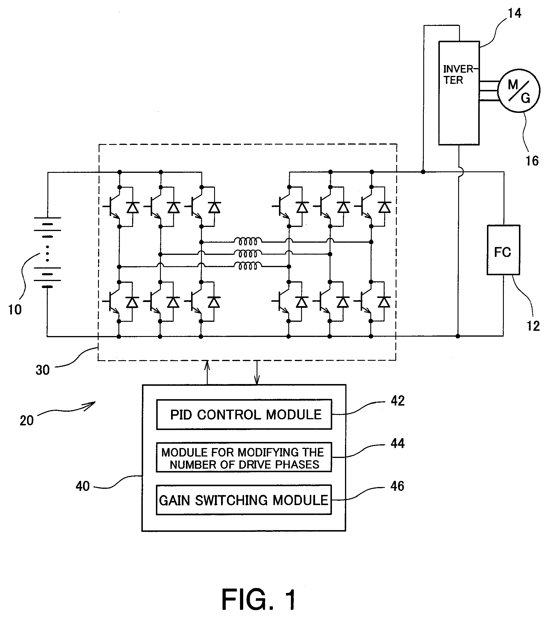
[0023]An embodiment according to the present invention will be described below in detail referring to the drawings. In the following description, a vehicle-mounted power supply system which is connected to a motor generator for driving a vehicle will be described as an example of a power supply system to which a converter control device is applied, however, a converter control device according to the present invention may applied to power supply systems other than vehicles. For example, the present invention may be applied to a power supply system or the like installed in building or the like. Furthermore, although an example in which a first power supply is a nickel hydride secondary battery and a second power supply is a solid polymer membrane fuel cell as the power supply system to which the converter control device is applied will be described, other types of power supplies may be employed. For example, a lithium ion battery can be used as the secondary battery, and fuel cells o...


PUM


Abstract

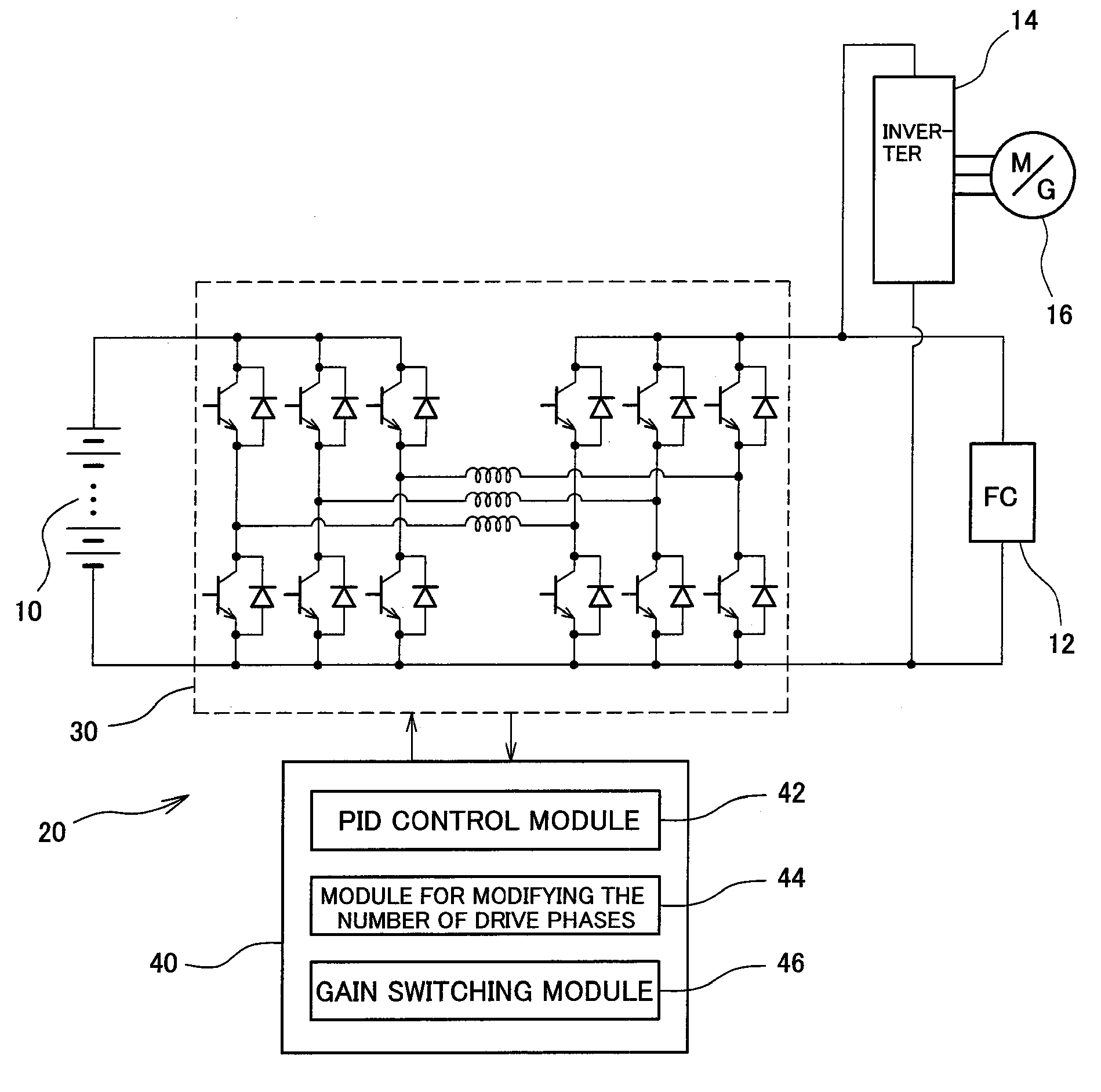
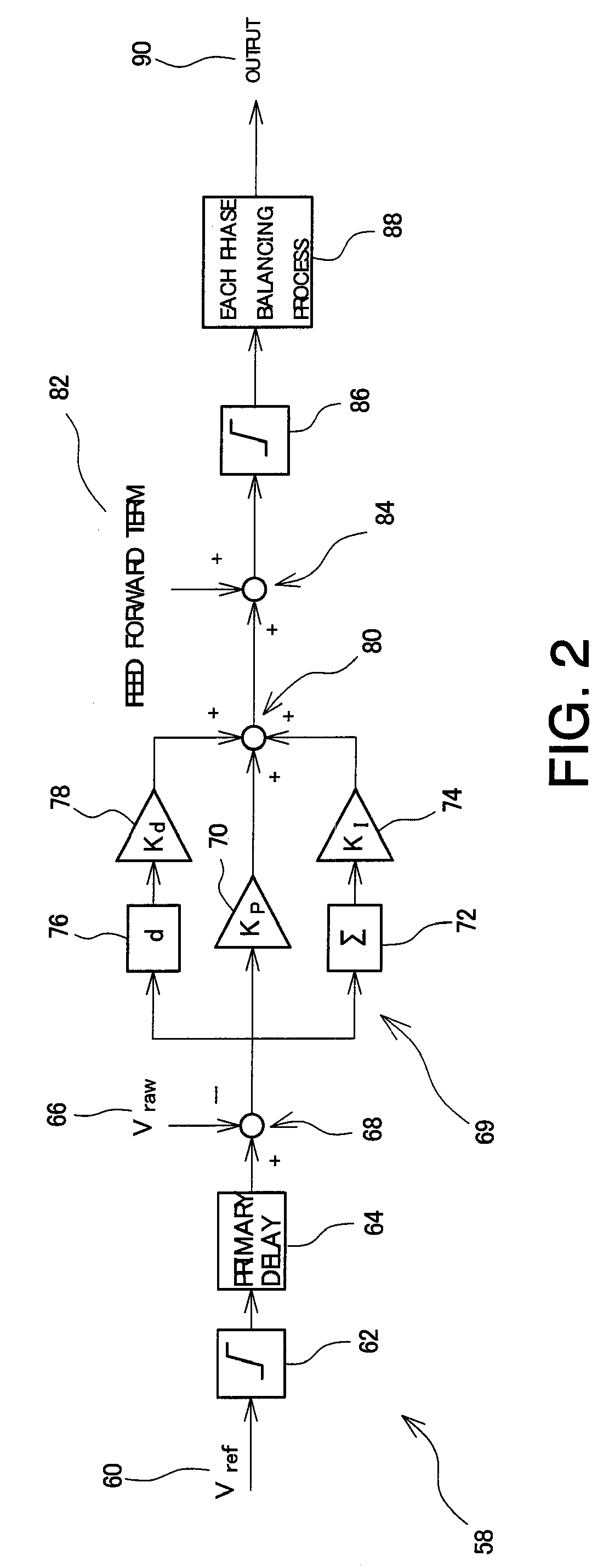
A converter device which is configured by connecting three converter circuits in parallel is provided between a secondary battery serving as a first power supply and a fuel cell serving as a second power supply. A control unit includes a PID control module which controls the converter device by PID control, for executing desired voltage conversion; a module for modifying the number of drive phases which changes the number of drive phases of the converter device in response to an electric power passing through the converter device; and a gain switching module which switches feedback gains in the PID control when the number of drive phases is changed.

Description

[0001]This is a 371 national phase application of PCT / JP2007 / 069535 filed 01 Oct. 2007, claiming priority to Japanese Patent Application No. JP 2006-278959 filed 12 Oct. 2006, the contents of which are incorporated herein by reference.TECHNICAL FIELD[0002]The present invention relates to a converter control device and, more particularly, to a converter control device which is connected between a first power supply and a second power supply, includes a converter device configuration in which a plurality of converters each having a plurality of switching elements and a reactor and performing voltage conversion bi-directionally are connected in parallel, and changes the number of converter phases to be driven in response to an electric power passing through the converter device.BACKGROUND ART[0003]In a power supply system which uses a fuel cell, in order to keep pace with load fluctuations that exceed electric generation capacity of the fuel cell, it is common for electrical power to b...

Claims


Application Information

Patent Timeline
Patent Type & Authority Patents(United States)
IPC IPC(8): H02M5/00G05F1/10
CPCH02M3/1584H02J2001/004H02M3/1582H02J2300/30H02M3/155H02M7/48
Inventor MANABE, KOTAHASEGAWA, TAKAHIKOMAENAKA, TAKESHI
Owner TOYOTA JIDOSHA KK
Learn More