
Composition and method for treating a subterranean formation

a subterranean formation and composition technology, applied in the direction of fluid removal, chemistry apparatus and processes, borehole/well accessories, etc., can solve the problems of high reactive acidity, failure to produce, and inability to form wormholes, etc., to achieve easy leakage control, reduce drag, and reduce friction pressure

Inactive Publication Date: 2008-06-03
SCHLUMBERGER TECH CORP
View PDF12 Cites 38 Cited by
  • Summary
  • Abstract
  • Description
  • Claims
  • Application Information

AI Technical Summary

Benefits of technology

The present invention provides a stimulation method that uses a fluid system that is thermally stable, self-diverting, retarded, and low friction pressures. The method includes using a chelant system that has advantages over other methods, such as emulsified acids. A viscoelastic surfactant is added to facilitate leak off control, diversion, and drag reduction. The fluid system does not use mineral acid to react with the formation, reducing sludging. The method can be used for acid fracturing, acidizing, diversion, filter cake removal, and scale removal. The invention also provides an improved method for acid treatment of high temperature subterranean carbonate formations and a one-step method for high temperature carbonate matrix and fracture acidizing for both leak-off control and kinetic retardation. The method can achieve long etched fracture half lengths with a retarded acid system that is not hampered by high friction pressure / drag. The method can also remove filter cake while controlling excessive leak-off in situations where the filter cake is compromised as a result of erosion that occurs faster than expected.

Problems solved by technology

The failure to produce is typically due to an inadequate, or damaged, path for fluids to flow from the formation to the wellbore.
This damage may be because the formation inherently has insufficient porosity and / or permeability, or because the porosity and / or permeability have been decreased (damaged) near the wellbore during drilling and / or completion and / or production.
Acids normally used in field treatments are highly reactive at reservoir conditions and tend to form a limited number of wormholes.
However, unless the treatment is designed properly, wormholes are not formed.
However, when the pressure is released, the fracture typically closes and the new flow path is not maintained unless the operator provides some mechanism by which the fracture is held open.
At present, matrix acidizing treatments are plagued by at least three serious limitations: (1) inadequate radial penetration; (2) incomplete axial distribution; and (3) corrosion of the pumping and well bore tubing.
Although the following discussion will focus for the most part on matrix acidizing, similar problems affect acid fracturing methods such that the discussion is entirely applicable to both types of acid treatment.
The first problem with acid treatment, inadequate radial penetration, is caused by the reaction between the acid introduced into the formation and the material in the wellbore and / or formation matrix, with which it first contacts.
A second problem that limits the effectiveness of matrix acidizing technology is incomplete axial distribution.
This problem relates to the proper placement of the acid-containing fluid, i.e., ensuring that the fluid is delivered to the desired zone or zones (i.e., the zone that needs stimulation) rather than another zone or zones.
Thus, in many cases, a substantial fraction of the productive, hydrocarbon-bearing intervals within the zone to be treated are not contacted by enough acid to penetrate deep enough (laterally in the case of a vertical wellbore) into the formation matrix effectively to increase its permeability and therefore its capacity for delivering hydrocarbon to the wellbore.
This problem of proper placement is particularly vexing since the injected fluid preferentially migrates to higher permeability zones (the path of least resistance) rather than to lower permeability zones, yet it is those latter zones that require the acid treatment (i.e., because they are low permeability zones, the flow of hydrocarbon through them is diminished).
Emulsified acid systems and foamed systems are commercially available responses to the diversion problem, but operational complexity sometimes limits their use.
Gelling agents are commercially available, but are often undesirable in matrix acidizing since the increased viscosity makes the fluid more difficult to pump (i.e., the same resistance to flow that confers the pressure build-up in the formation and results in the desired diversion, actually makes these fluids difficult to place).
Some commercially available systems are polymeric cross-linked systems, i.e., they are linear polymers when pumped, but a chemical agent pumped along with the polymer causes the polymers to aggregate or cross-link once in the wellbore, which results in gelling.
Unfortunately, these systems leave a residue in the formation, which can damage the formation, resulting in diminished hydrocarbon production.
In addition, the success of these systems is naturally dependent upon a cross-linking reaction that can be difficult to optimize so that it is delayed during pumping but maximized once the chemicals are in the bottom or end of the wellbore, or in the formation.
This reaction is easily perturbed by formation chemistry, contaminants in the pumping equipment, and other factors.
Another limitation of acid treatments is the corrosion of the pumping equipment and well tubing and casing caused by contact with the acid (made worse by the use of concentrated solutions of mineral acids).
However, corrosion inhibitors can significantly increase the cost of acidizing treatments.
Another problem with acid treatments is iron precipitation, especially in sour wells (i.e., wells in which the hydrocarbon has a relatively high sulfur content) or carbonate formations.
There is a tendency for iron sulfide scale to form in boreholes and / or formations, especially in sour wells.
The acid used to treat the well can dissolve the iron sulfide, but in the process hydrogen sulfide is generated, which is toxic and stimulates corrosion.
Precipitation of iron is highly undesirable because of damage to the permeability of the formation.
Although the treatment fluid described in that patent can help control iron precipitation, in some situations effective control requires the use of so much material that the treatment cost becomes excessive; this is especially true for treatment fluids comprising EDTA, which has relatively low solubility in acid (e.g., pH≦4).
Another limitation of known acid treatments is their susceptibility to the temperature of the subterranean formation.
In some acid treatments, the high temperature has a tendency to accelerate corrosion of metal in the wellbore.

Method used


Image

  • Composition and method for treating a subterranean formation
  • Composition and method for treating a subterranean formation

Examples


example 1

[0044]An initial bench-top, small-scale experiment was performed by preparing a live acid formulation with 20% HEDTA dissolved in water and reduced in pH from about 12 to about 2.8 with HCl. 1% methanol, 0.2 to 0.4% corrosion inhibitor, and 7.5% BET-0-40 were added and agitated in a jar. A light gel was formed with a viscosity of about 100 cP, at 170 sec-1 at room temperature (estimated, as the sample was not large enough to measure). The formulation was spent using two spatula-fulls of powdered calcium hydroxide with mild agitation performed by shaking the jar. After about one minute, no visible signs of additional thickening were observed. However, after 2-3 minutes, a thick fluid that hung on the lip of the jar when the jar was tilted as if to pour out any liquid therein, reminiscent of heavily crosslinked fracturing gels, was produced.

example 2

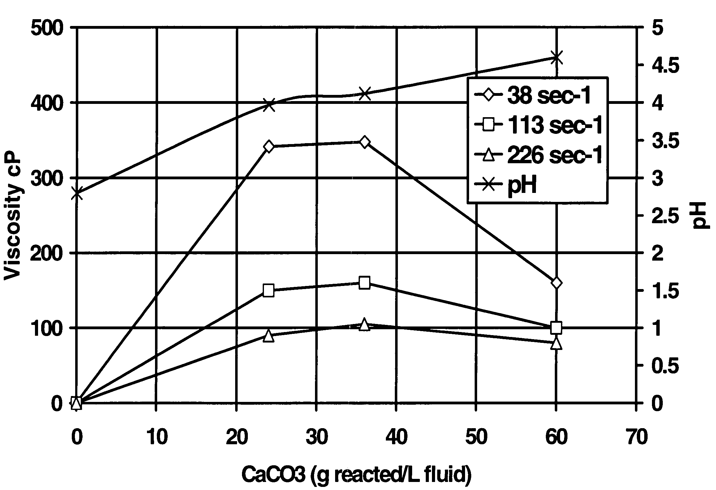
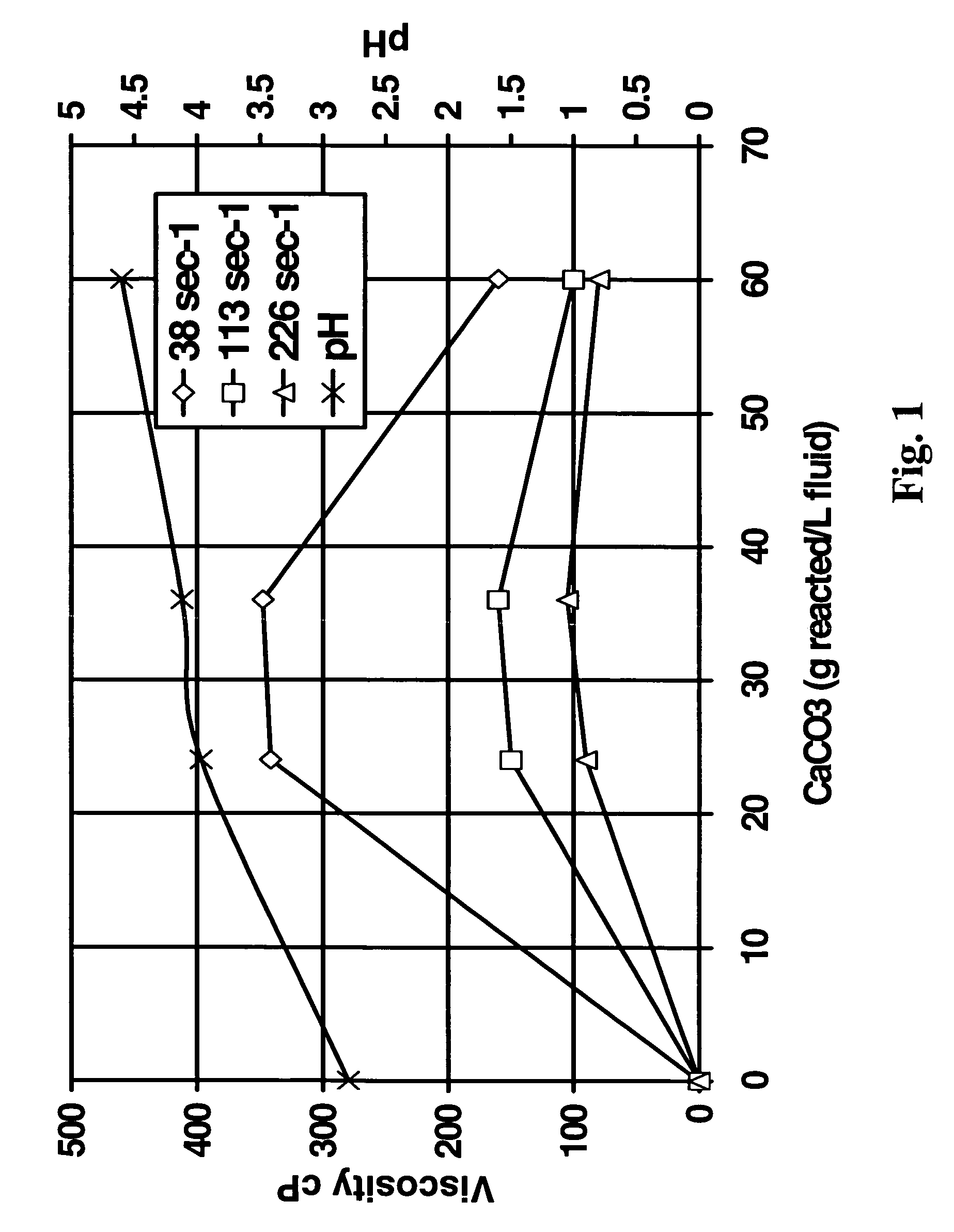
[0045]The second test was a test to determine the feasibility of using the method of the present invention in reservoirs (simulated with crude oil) having a high tendency to generate sludge and / or precipitate asphaltenes in the presence of highly concentrated HCl or organic acid blend. A fluid was prepared starting with aqueous 20% HEDTA reduced to a pH of about 2.8 with hydrochloric acid, 1% methanol, 2.6% corrosion inhibitor, 0.3% non-emulsifier, and 7.5% BET-O-40 in the presence of 1000 ppm Fe+++. As shown in FIG. 1, the system gelled in the presence of CaCO3; the change in viscosity was more pronounced at low sheer. The x-axis in FIG. 1 is the grams of CaCO3 reacted per L of this fluid.

example 3

[0046]A test was conducted to ascertain the corrosive effect of the fluid system utilized in practicing the method of the present invention as follows. Fluids were prepared with reagent grade chemicals diluted with tap water. One inch by 1.5 inch (2.5 cm×3.8 cm) test coupons of L80 and P110 steels were numbered for identification, cleaned, rinsed in acetone, dried and weighed, and then stored in a desiccator until use. Corrosivity was evaluated in an autoclave at 270° F. (132° C.) with exposure time to six hours at 3000 psi (20.7 MPa). Following the test, the coupons were rinsed in acetone and scrubbed with soap and water to remove inhibitor film and corrosion deposits. A final rinse in acetone was completed prior to re-weighing the metal coupons to calculate corrosion rates. The corrosion rates observed are shown below with a pitting index score by which (a pitting index of 3 or less is considered acceptable) determined by the size and depth of pits as shown in the following table:...


PUM


Abstract

A method of treating a subterranean formation with a retarded self-diverting fluid system. The method includes contacting the formation with a mixture of acid, chelating agent, and betaine surfactant in which the betaine surfactant is mixed with an aqueous solution of the chelating agent in which the pH has been adjusted to a pH of below about 3.0, but above the pH at which the free acid of the chelating agent precipitates, and the resulting fluid system is utilized for both acid fracturing and matrix stimulation, as well as workover procedures such as scale and filter cake removal, especially in high temperature formations.

Description

BACKGROUND OF THE INVENTION[0001]The present invention relates to a self-diverting retarded formation-dissolving composition for treating a subterranean formation, particularly at high temperatures. It also relates to methods for acid fracturing and matrix acidizing using the composition.[0002]The flow of fluids through porous media, for example the production of fluids from wells, is governed by three principle factors: the size of the flow path, the permeability of the flow path, and the driving force. It is often necessary to stimulate the production of fluids from subterranean formations when wells are not producing satisfactorily. The failure to produce is typically due to an inadequate, or damaged, path for fluids to flow from the formation to the wellbore. This damage may be because the formation inherently has insufficient porosity and / or permeability, or because the porosity and / or permeability have been decreased (damaged) near the wellbore during drilling and / or completio...

Claims


Application Information

Patent Timeline
Patent Type & Authority Patents(United States)
IPC IPC(8): E21B43/02
CPCC09K8/52C09K8/68
Inventor BRADY, MARKMILNE, ARTHUR
Owner SCHLUMBERGER TECH CORP
Learn More