
Spin-polarization devices using rare earth-transition metal alloys

a metal alloy and rare earth technology, applied in the field of rare earth-transition metal alloys, can solve the problems of poor growth quality of srruo/sub>3/sub>, low tsp of ni and these alloys, and inapplicability of srruo/sub>3/sub> for device applications

Active Publication Date: 2007-06-12
IBM CORP
View PDF16 Cites 159 Cited by
  • Summary
  • Abstract
  • Description
  • Claims
  • Application Information

AI Technical Summary

Benefits of technology

The patent describes a device that includes a rare earth element-transition metal alloy in a tunnel barrier and a magnetic layer. The device has a negative tunneling magnetoresistance at one temperature and a positive tunneling magnetoresistance at another temperature. The device also includes a second layer of magnetic material and a third layer of magnetic material, which form a magnetic tunnel junction. The device can be used in a magnetic tunnel junction device. The technical effects of the invention include improved magnetic tunnel junction performance and the ability to control spin-polarized current at room temperature.

Problems solved by technology

Although Ni and Ni-rich alloys often show low TSP values as compared with Fe and Co-rich alloys, this is most likely due to problems in creating a high quality interface with the tunneling barrier.
However, the TSP of Ni and these alloys was very low, and it is now believed that the proportionality of TSP and the magnetic moment observed in these alloys was an artifact of intermixing at the F / I interface and the relatively poor quality of the growth of these structures.
Moreover, SrRuO3 is not useful for device applications, since its Curie temperature is well below room temperature (˜150 K).
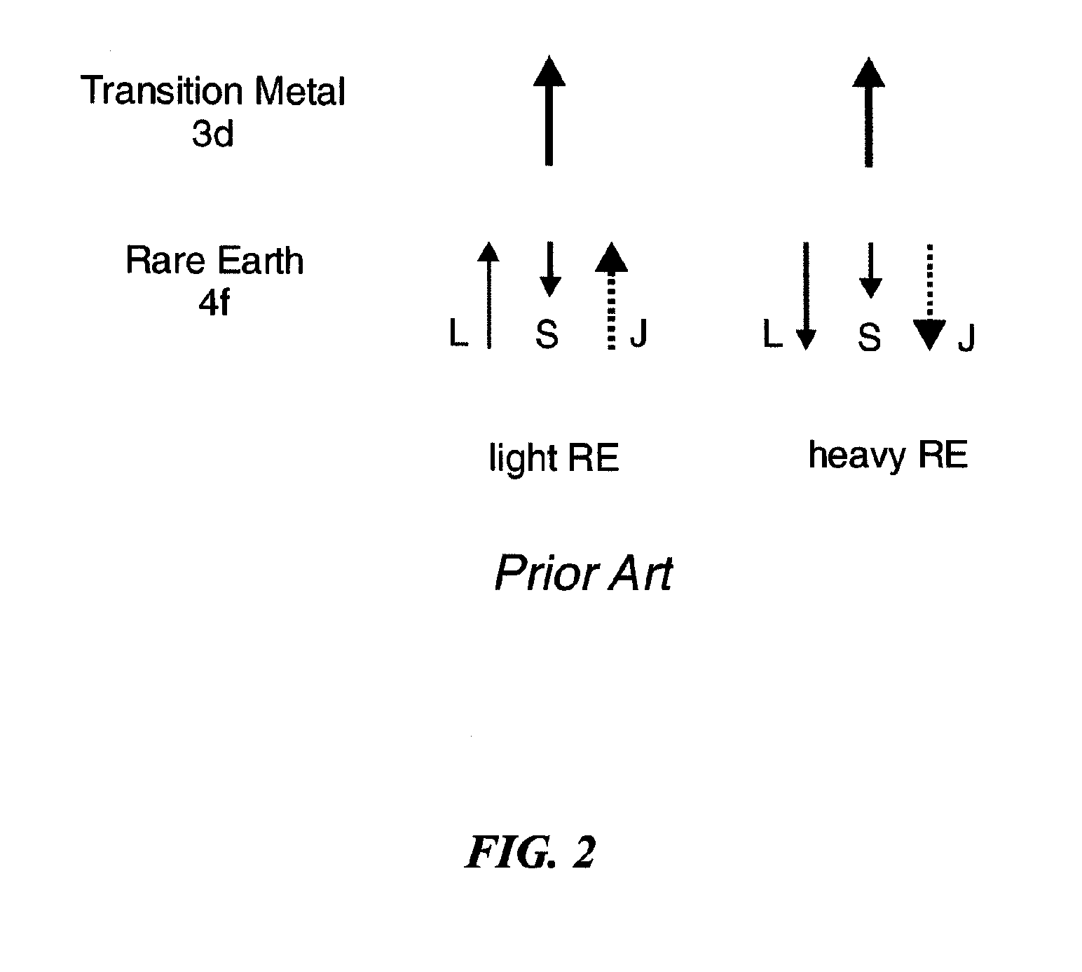
However, in amorphous alloys, the situation is more complicated than depicted in FIG. 2.
However, short range order can introduce a local field which can give rise to anisotropy even in the absence of crystallinity.
The heat of formation of RE oxides is very high, so that there was a presumption that RE metals adjacent to an oxide tunnel barrier would likely be oxidized so inevitably reducing the spin polarization.
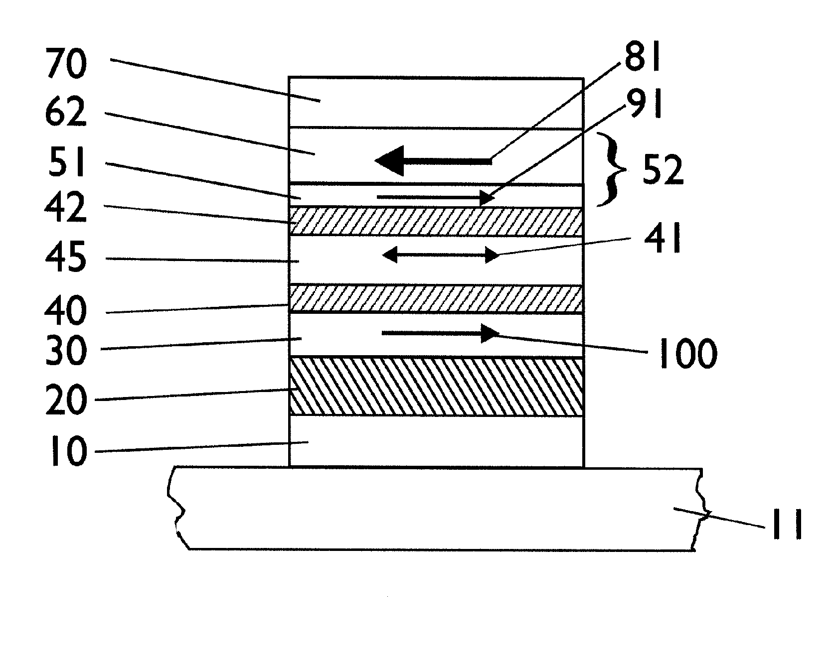
Such structures use very thin antiferromagnetically coupling films just a few angstroms thick, which are not necessarily highly thermally stable.

Method used


Image

  • Spin-polarization devices using rare earth-transition metal alloys
  • Spin-polarization devices using rare earth-transition metal alloys
  • Spin-polarization devices using rare earth-transition metal alloys

Examples


Embodiment Construction

[0063]The tunneling spin polarization of various RE—TM alloys was measured using superconducting tunneling spectroscopy (STS). Although these measurements are carried out at low temperatures and large magnetic fields, these studies allow the direct determination of the spin polarization of electrons tunneling from the RE—TM layer. The tunneling magnetoresistance of MTJ devices incorporating such layers is related to the magnitude of the spin polarization through Julliere's formula. However, the STS structures are in many ways simpler than MTJ devices with regard to the control of the magnetic orientation of the magnetic electrodes, so such studies provide a more direct and reliable measurement of the spin polarization of the tunneling current.

[0064]FIG. 4 shows the TSP measured at a temperature of 0.25 K and in an in-plane magnetic field of 2 T for Co—Gd alloys of various compositions using either Al2O3 or MgO tunnel barriers (I). The STS samples are comprised of shadow masked ferro...


PUM

PropertyMeasurementUnit
Curie temperatureaaaaaaaaaa
magnetizationaaaaaaaaaa
crystallization temperatureaaaaaaaaaa

Abstract

A tunnel barrier in proximity with a layer of a rare earth element-transition metal (RE—TM) alloy forms a device that passes negatively spin-polarized current. The rare earth element includes at least one element selected from the group consisting of Gd, Tb, Dy, Ho, Er, Tm, and Yb. The RE and TM have respective sub-network moments such that the absolute magnitude of the RE sub-network moment is greater than the absolute magnitude of the TM sub-network moment. An additional layer of magnetic material may be used in combination with the tunnel barrier and the RE—TM alloy layer to form a magnetic tunnel junction. Still other layers of tunnel barrier and magnetic material may be used in combination with the foregoing to form a flux-closed double tunnel junction device.

Description

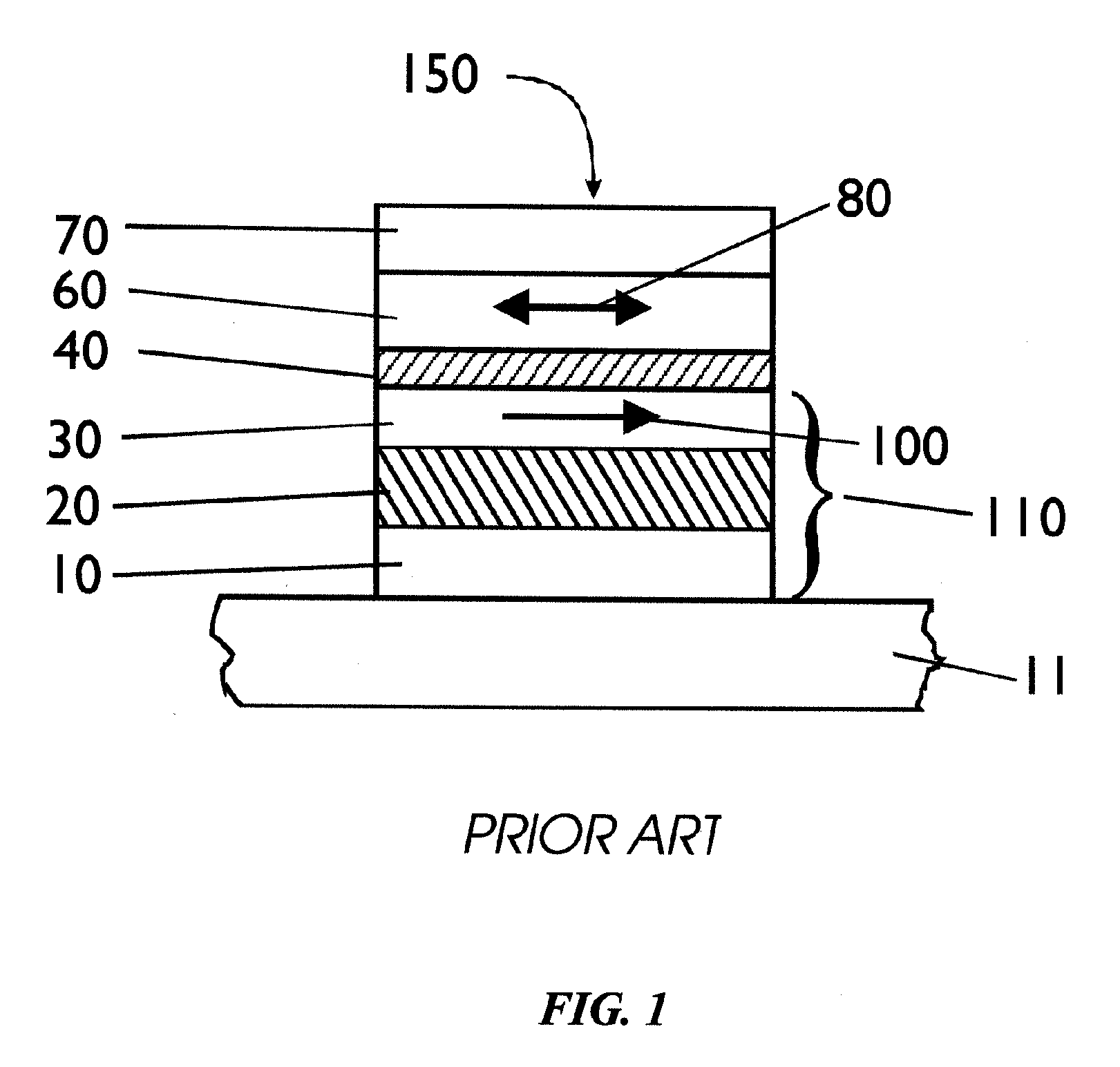
[0001]The U.S. Government has a paid-up license in this invention and the right in limited circumstances to require the patent owner to license others on reasonable terms as provided for by the terms of contract MDA972-01-C-0051 awarded by DARPA.TECHNICAL FIELD[0002]The invention relates to devices that pass spin-polarized current, such as magnetic tunnel junctions, and more particularly to the use of rare earth-transition metal alloys in such devices.BACKGROUND OF THE INVENTION[0003]Magnetic tunnel junctions (MTJs) generally consist of sandwiches of two thin ferromagnetic (FM) metallic films separated by a thin (e.g., ˜5-30 Å) insulating barrier (I). Application of a voltage bias across the electrodes leads to a tunneling current whose magnitude depends on the relative orientation of the magnetic moments of the two ferromagnetic layers. For conventional ferromagnetic metals (e.g., Co, Fe, and Ni and their binary or ternary alloys) the resistance is usually higher when the magnetiza...

Claims


Application Information

Patent Timeline
Patent Type & Authority Patents(United States)
IPC IPC(8): H01L29/06H01L29/08H01L39/00H10N60/00
CPCH01L43/08H01L43/10H10N50/85H10N50/10
Inventor KAISER, CHRISTIANPARKIN, STUART STEPHEN PAPWORTH
Owner IBM CORP
Learn More