
Method and system for constructing large, continuous, concrete slabs

a technology of continuous concrete and construction method, which is applied in the direction of paving reinforcement, building repair, etc., can solve the problems of large concrete slab, visible cracks in concrete slabs and pavements, and continuous pavements such as concrete roadways and paths that will crack,

Inactive Publication Date: 2006-07-04
BUILDING INNOVATIONS PTY LTD
View PDF50 Cites 6 Cited by
  • Summary
  • Abstract
  • Description
  • Claims
  • Application Information

AI Technical Summary

Benefits of technology

[0012]It is an object of the invention to provide a method and a system for constructing a large continuous concrete slab that overcomes or at least minimizes a disadvantage referred to above.
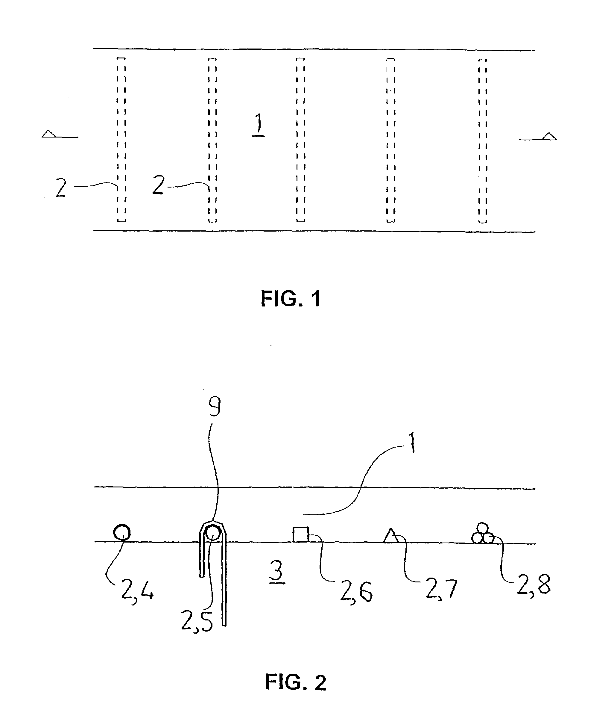
[0017]wherein the inducers are of a size, shape and spacing to promote fine cracking in their vicinity throughout the area of the slab, such that the slab has a continuous top surface and does not require the installation of shrinkage control joints through the top surface to prevent uncontrolled cracking.
[0031]Preferably, each arm comprises two blades that intersect at a midpoint such that an end of each arm is cross-shaped when viewed in transverse cross section. Such a configuration enables crack inducers with slightly different diameters to be readily attached. The blades can also have ends that are tapered to facilitate attachment. Preferably, the connector has four arms extending radially from the body. The blades can also comprise flexible or flexibly resilient material, so as to facilitate attachment.

Problems solved by technology

Large concrete slabs such as commercial, retail and industrial floors, and continuous pavements such as concrete roadways and paths will crack during the hydration period due to drying shrinkage of the concrete and other effects if they are not detailed to accommodate the shrinkage strains.
In the absence of shrinkage control joints, cracks will typically occur in concrete slabs and pavements in the first three months after placing, and these cracks will normally meander through the concrete at random locations.
Uncontrolled, visible cracks in concrete slabs and pavements are generally perceived by those observing them as ugly at best and as failures at worst.
Furthermore, the uncontrolled cracks are weak regions, which may fail under load, and uncontrolled cracks will widen and crumble under heavy traffic.
Although vastly superior to uncontrolled cracking, conventional control joints are expensive to install, and they are often the first point of failure in floor slabs and pavements.
The control joints are vulnerable to damage in traffic areas, usually due to impact, and they become unsightly when the slab edges break away and when sealants fail.
They can also be a hazard for pedestrians and some random cracks often still occur despite the installation of a pattern of control joints.
Such a joint does not prevent cracking, but attempts to limit cracking to the saw cut locations and generally attempts to control cracking to straight lines.
Unfortunately, this method is time consuming and involves a worker revisiting the slab after it has set to install the saw cut, and yet again to install the sealant.
The additional time and material add to the cost of preparing the concrete slab.
Using the invention of this patent, however, requires additional time and materials, and the use of joints.

Method used


Image

  • Method and system for constructing large, continuous, concrete slabs
  • Method and system for constructing large, continuous, concrete slabs
  • Method and system for constructing large, continuous, concrete slabs

Examples


example

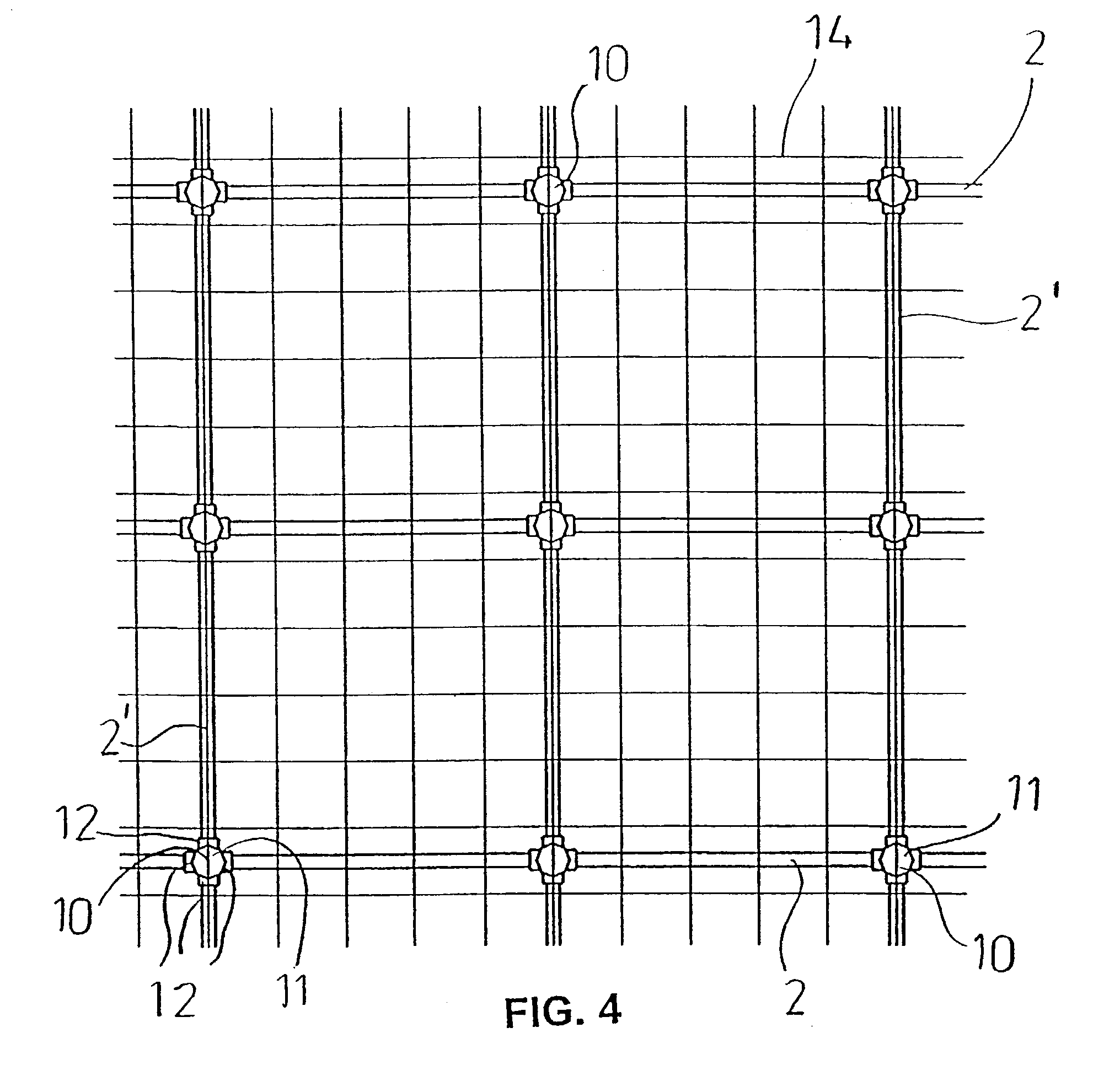
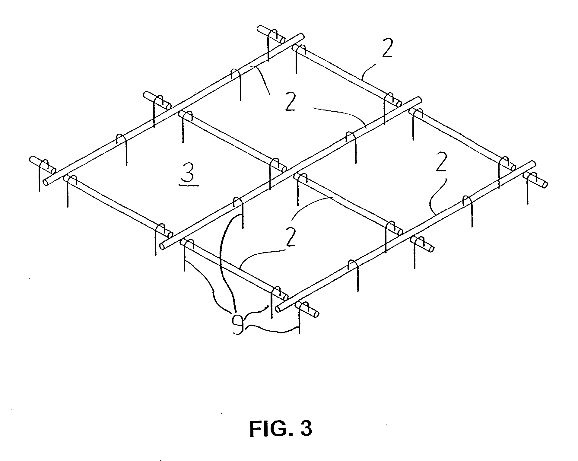
[0084]A specific example of slab construction will now be described. The crack inducer system has been used to construct a 4,042 square meter floor area for a supermarket, without control joints. The slab was 125 mm thick throughout and was reinforced with F62 mesh placed with about 30 mm top cover. A grid of crack inducers was used to induce closely spaced fine cracks throughout the area of the slab. The crack inducer grid comprised 33 mm diameter PVC pipes at 1 m centers in both x and y planar directions, the diameter of the pipes being approximately 25% of the thickness of the slab. Four-way connectors were used to connect the crack inducers and to provide a surface at 70 mm above the concrete-pouring surface to support the reinforcing mesh. The slab extended throughout the entire area of the supermarket, including the trading area, the cool rooms, the food preparation areas, and the reserves area.

[0085]Some of the advantages of the system for constructing slabs on grade can be s...


PUM

PropertyMeasurementUnit
Lengthaaaaaaaaaa
Lengthaaaaaaaaaa
Lengthaaaaaaaaaa

Abstract

A method and system are provided for constructing large, continuous, concrete slabs without using conventional shrinkage joints. The system comprises a grid of closely-spaced crack inducers (2) arranged relative to a concrete-pouring surface and adapted to be covered by concrete. The crack inducers (2) may be connected to one another with connectors (10). The crack inducers (2) are of a size, shape and spacing to promote formation of fine cracks in the vicinity of the inducers (2) throughout the slab when the concrete sets.

Description

CROSS-REFERENCE TO RELATED APPLICATIONS[0001]This is a continuation of International Patent Application No. PCT / AU01 / 00950, filed Aug. 3, 2001, which was published in the English language on Feb. 14, 2002 under International Publication No. WO 02 / 12630 A1, and the disclosure of which is incorporated herein by reference.BACKGROUND OF THE INVENTION[0002]This invention relates to a method and to a system for constructing large continuous concrete slabs using closely spaced, cast-in crack inducers.[0003]Large concrete slabs such as commercial, retail and industrial floors, and continuous pavements such as concrete roadways and paths will crack during the hydration period due to drying shrinkage of the concrete and other effects if they are not detailed to accommodate the shrinkage strains. In the absence of shrinkage control joints, cracks will typically occur in concrete slabs and pavements in the first three months after placing, and these cracks will normally meander through the conc...

Claims


Application Information

Patent Timeline
IPC IPC(8): E04C5/16E01C7/14E01C9/00E01C11/10E01C11/18E02D27/01E04B1/62E04B5/32E04C5/04E04G9/10E04G21/02
CPCE01C9/001E01C11/106E04C5/04E02D27/01E01C11/18
Inventor COLEFAX, WARWICK IANCOLEFAX, ROBERT FOSTERGETALDIC, MIRO
Owner BUILDING INNOVATIONS PTY LTD
Learn More