Eureka AIR delivers breakthrough ideas for toughest innovation challenges, trusted by R&D personnel around the world.

System and method for fabricating or repairing a part

a technology for fabricating or repairing parts, applied in the field of rapid manufacturing, can solve the problems of affecting the shape of the underlying material, not having enough heat, and droplets with relatively small diameters, and achieve the effect of improving the geometric accuracy of parts

Inactive Publication Date: 2006-03-28
SOUTHERN METHODIST UNIVERSITY
View PDF14 Cites 294 Cited by
  • Summary
  • Abstract
  • Description
  • Claims
  • Application Information

AI Technical Summary

Benefits of technology

[0008]Embodiments of the invention provide a number of technical advantages. Embodiments of the invention may include all, some, or none of these advantages. According to one embodiment of the invention, a system for manufacturing or repairing parts produces better accuracy than a purely additive solid freeform fabrication (“SFF”) process due to the introduction of intermediate material removal procedures. In addition, the materials and deposition methods utilized are not constrained by the resolution of the deposition, since the accuracy of the parts is controlled by the shaping processes. Another technical advantage is that no custom fixturing is required. Fixtures are inherent in the additive / subtractive manufacturing method; support structures and all previously built layers automatically serve as fixtures for the subsequent layers. Employing an additive / subtractive manufacturing method also opens up the engineering design space. Parts may be embedded with prefabricated components, such as electronic devices or sensors. In addition, it is capable of constructing internal intricate features as well as integrated assembly mechanisms.
[0010]According to another embodiment of the invention, a closed-loop control system based on infrared image sensing for controlling the size of the molten pool in a laser-based additive manufacturing (“LBAM”) process improves the geometrical accuracy of parts and simultaneously provides the desired microstructure.
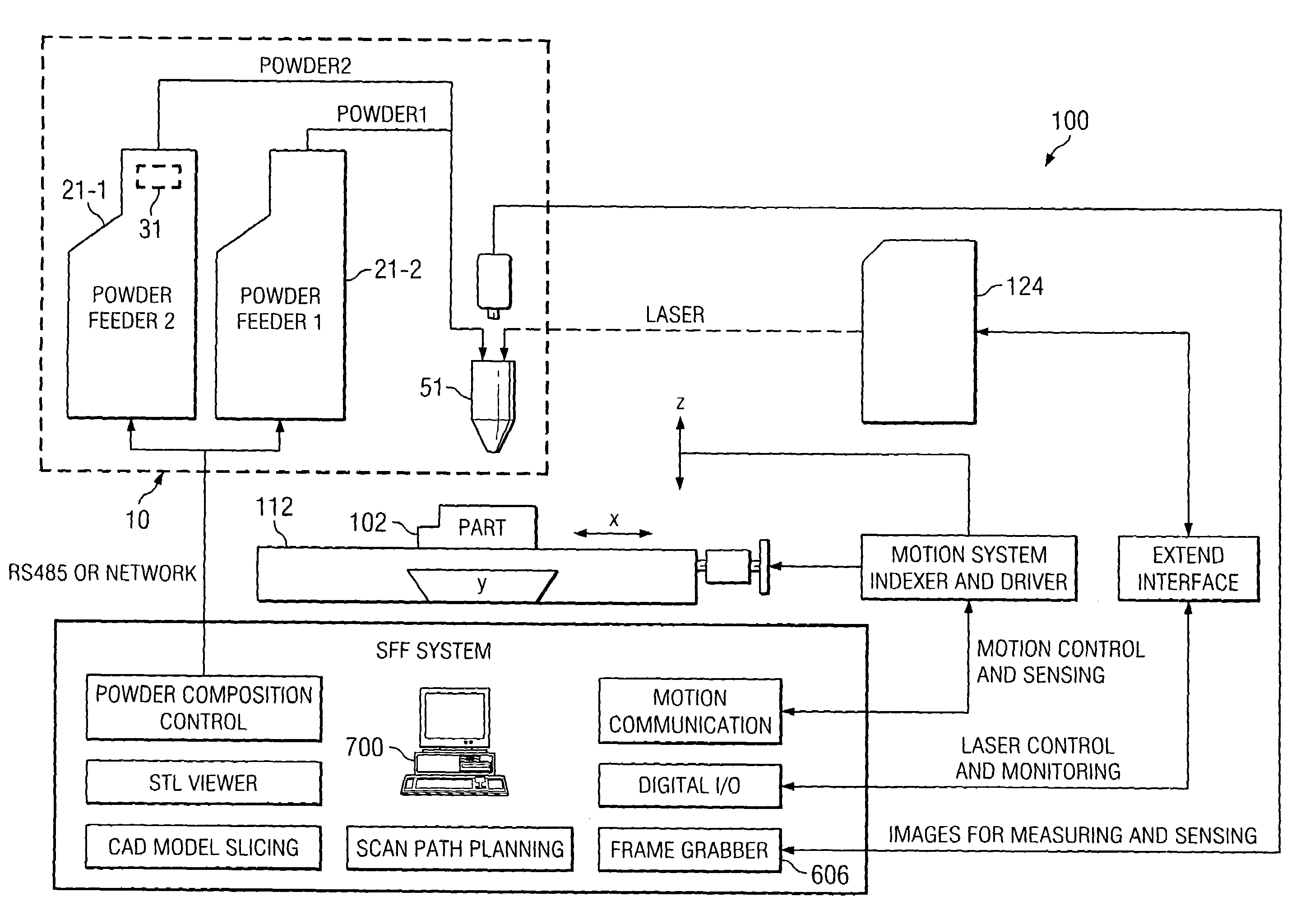
[0011]According to another embodiment of the invention, a powder delivery system permits precise control of a metering device that is continuously fed or dosed from a hopper with an amount of a powder that is delivered to a molten pool formed on a functional component and / or sacrificial substrate component in a LBAM process or apparatus. Such a powder delivery system may be used to produce a functional part, including a functionally gradient part (“FGP”), having desired chemical and / or mechanical properties.

Problems solved by technology

An important issue in applying a thermal deposition technique for the SFF of metallic parts is to control the thermal gradients caused by fusing molten droplets onto previously deposited layers.
Thermal spraying creates molten droplets with relatively small diameters (about 50 microns) which do not possess enough heat to re-melt the underlying surface.
But the large heat transfer affects the shape of the underlying material.
However, this process as a SFF method is limited by the size of the parts, the deposition rate, and high cost.

Method used


Image

  • System and method for fabricating or repairing a part
  • System and method for fabricating or repairing a part
  • System and method for fabricating or repairing a part

Examples


Embodiment Construction

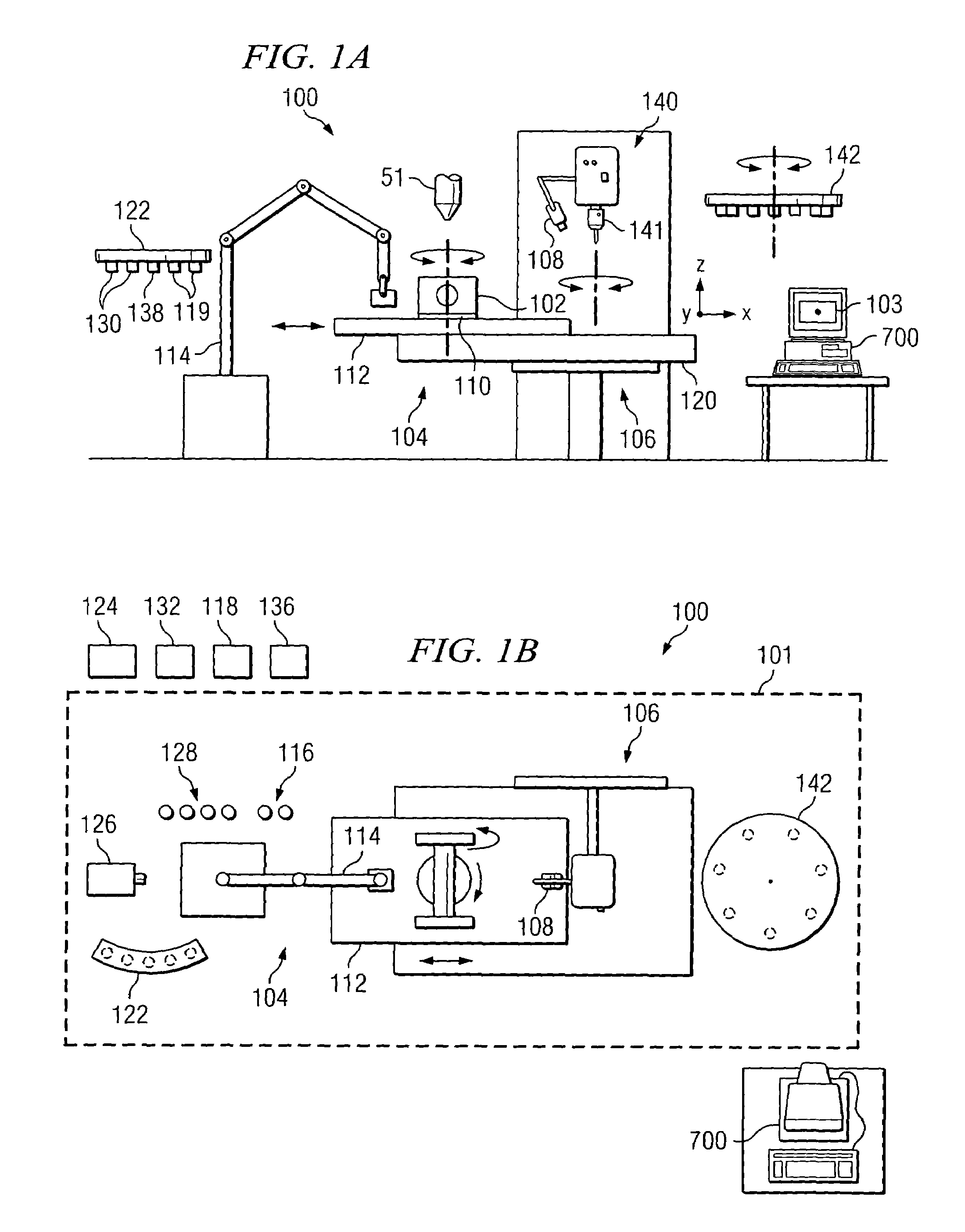
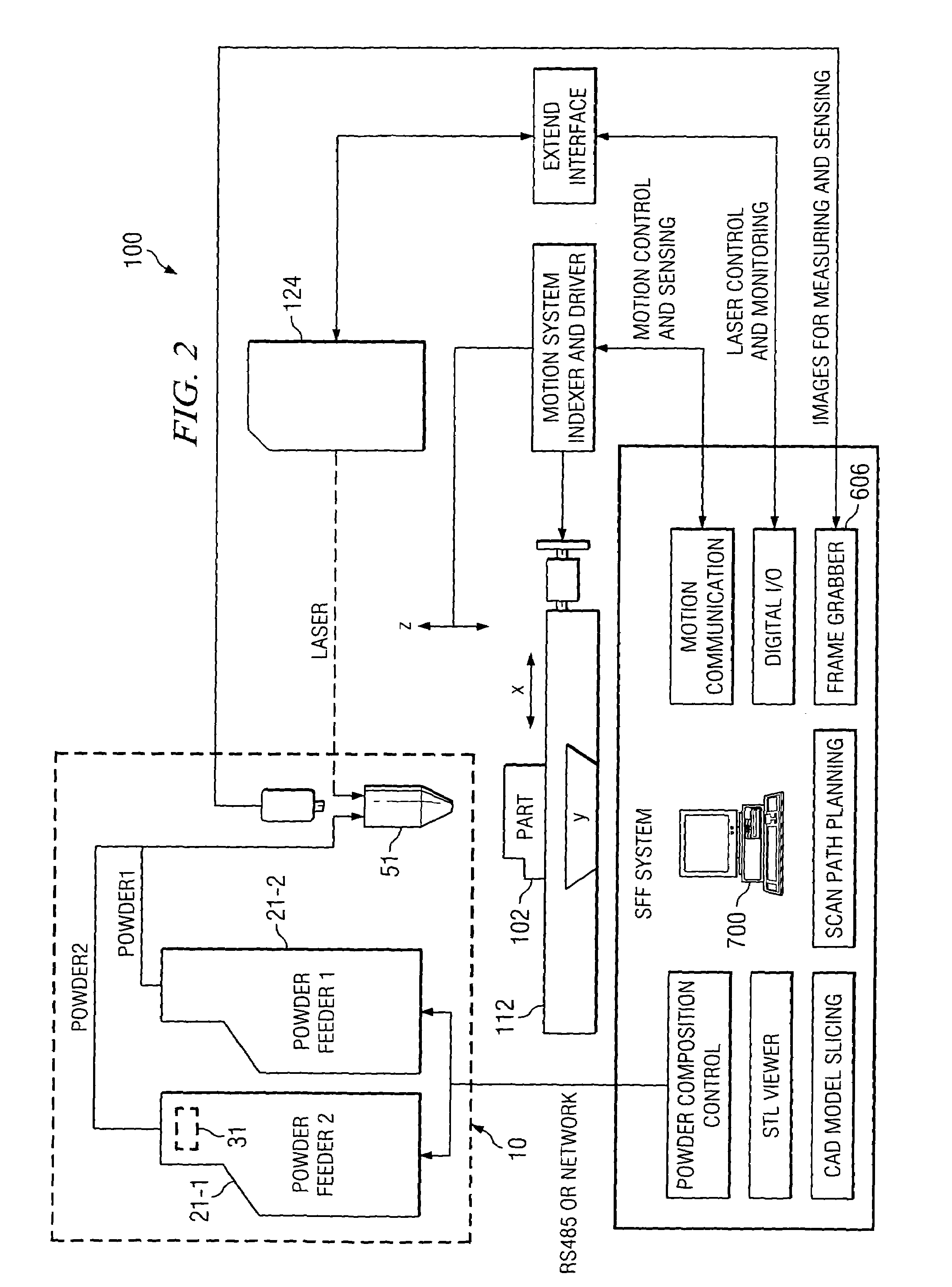
[0025]Example embodiments of the present invention and their advantages are best understood by referring now to FIGS. 1A through 9 of the drawings, in which like numerals refer to like parts.

[0026]FIGS. 1A and 1B are elevation and plan views, respectively, of a system 100 for manufacturing or repairing parts according to one embodiment of the invention. As described below, this multi-fabrication system provides the capability to make complex parts having internal and external geometric features with high dimensional accuracy and superior surface quality. For example, the same setup for one computer controlled system platform, system 100 may perform the following operations: four additive operations and / or their combination, a plurality of subtractive operations, in-process and post-process inspection, and scanning for reverse engineering. The combination of additive and subtractive processes exhibits some technical advantages, such as the production of more accurate complex parts, a...


PUM

PropertyMeasurementUnit
diametersaaaaaaaaaa
radiation wavelengthaaaaaaaaaa

Abstract

According to one embodiment of the invention, a system for fabricating a part includes a computer operable to control the fabrication of a three-dimensional part using a solid CAD model, a deposition station operable to deposit successive two-dimensional layers of material to fabricate the three-dimensional part, and a machining station operable to remove at least a portion of one or more of the deposited two-dimensional layers of material. The deposition station includes a substrate on which to fabricate the three-dimensional part, a welding-based deposition system having a welding torch, a laser-based deposition system having a laser head, a plasma powder cladding system having a plasma torch, and a multi-axis robot operable to, when directed by the computer, utilize one of the welding-based deposition system, laser-based deposition system, and plasma powder cladding system to deposit any of the two-dimensional layers of material. The machining station includes a multi-axis milling machine and an automatic tool changer. The milling machine is operable to, when directed by the computer, select from a plurality of machining tools associated with the automatic tool changer for use in the milling machine.

Description

CROSS-REFERENCE TO RELATED APPLICATION[0001]This application claims the benefit of Ser. No. 60 / 414,639, entitled “POWDER DELIVERY SYSTEM,” filed provisionally on Oct. 1, 2002.TECHNICAL FIELD OF THE INVENTION[0002]This invention relates generally to the field of rapid manufacturing and, more specifically, to a system and method for fabricating or repairing a part.BACKGROUND OF THE INVENTION[0003]Solid Freeform Fabrication (“SFF”) is a set of manufacturing processes that produce complex solid objects directly from geometric models without specific part or tooling information. SFF builds up 3D objects by successive 2D layer deposition. Objects are sliced into 2D thin layers and each layer is built by various deposition or forming processes. Deposition methods may include solidification of liquid resins with ultraviolet radiation, such as stereolithography, sintering of powders with laser scans, such as selective laser sintering, and extrusion of heated thermoplastic polymers, such as f...

Claims


Application Information

Patent Timeline
Patent Type & Authority Patents(United States)
IPC IPC(8): G06F19/00
CPCB22F3/1055B23K26/0884B23K26/1482B22F2003/247B22F2998/00B22F2998/10B22F2003/1059Y10T483/17B22F2202/11B22F2202/13B22F3/24B33Y10/00B33Y30/00B33Y40/00Y02P10/25B22F10/66B22F12/70B22F12/55B22F10/32B22F12/52B22F12/90B22F10/36B22F10/25B22F12/41B22F12/57B22F12/53B33Y40/20B33Y50/02
Inventor KOVACEVIC, RADOVANVALANT, MICHAEL E.
Owner SOUTHERN METHODIST UNIVERSITY
Why Eureka
Eureka Blog
Learn More