
Programmable frequency divider with symmetrical output

a frequency divider and symmetric output technology, applied in the field of integrated circuit frequency dividers, can solve the problems of less physical area and less power dissipation, and achieve the effects of overcoming inherent limitations in divide resolution, high divisor value, and flexible operation

Active Publication Date: 2005-11-01
MARVELL ASIA PTE LTD
View PDF6 Cites 20 Cited by
  • Summary
  • Abstract
  • Description
  • Claims
  • Application Information

AI Technical Summary

Benefits of technology

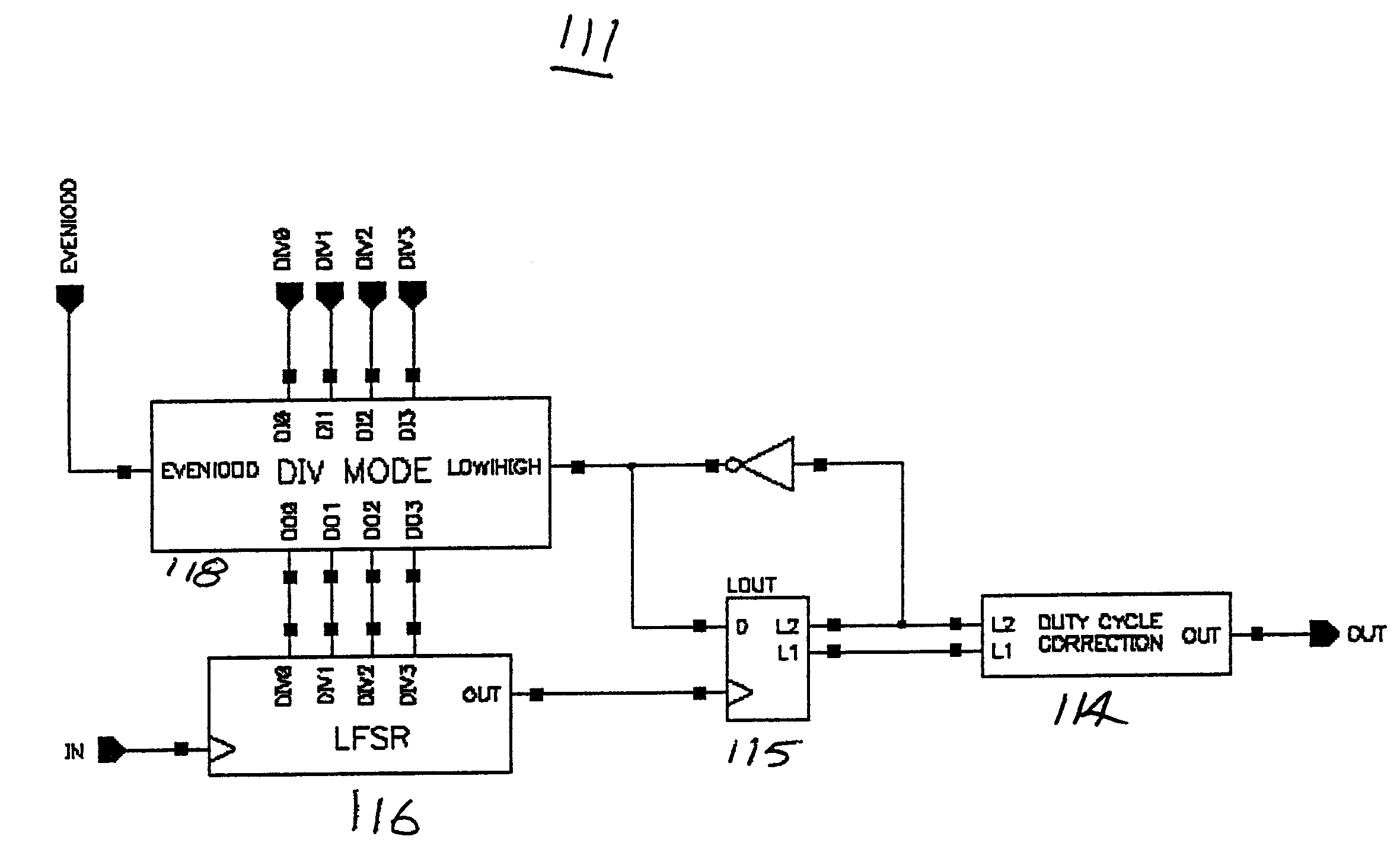
[0012]The present invention is directed toward a programmable frequency divider circuit capable of maintaining an output with a fifty-percent duty cycle. The frequency divider includes a non-symmetrical LFSR based component operated in series with a symmetrical divider component. The LFSR component of the present invention provides the means to achieve very high divisor values for the circuit, while the symmetrical divider component converts the asymmetrical output of the LFSR divider into a symmetrical output with a fifty-percent duty cycle. Both the LFSR divider and the symmetrical divider may be programmed to provide flexibility of divide operation via input control bits.
[0013]The present invention also employs a technique to dynamically adjust the divisor of the LFSR based divider component to overcome inherent limitations in the divide resolution due to the series combination of dividers. The divide resolution can be restored to a value as low as one allowing the disclosed divider to provide both even and odd divisor values.
[0014]By relegating the bulk of the division process to the LFSR based component, the frequency divider of the present invention can operate at high speed. In addition, the design requires fewer logic elements in the data path compared with prior art designs, thereby consuming less physical area and dissipating less power. The design architecture also lends itself to the performance of higher level functions, such as the synchronization of multiple divider outputs, dynamic switching of divisor values and the generation of multi-phase and spaced outputs.
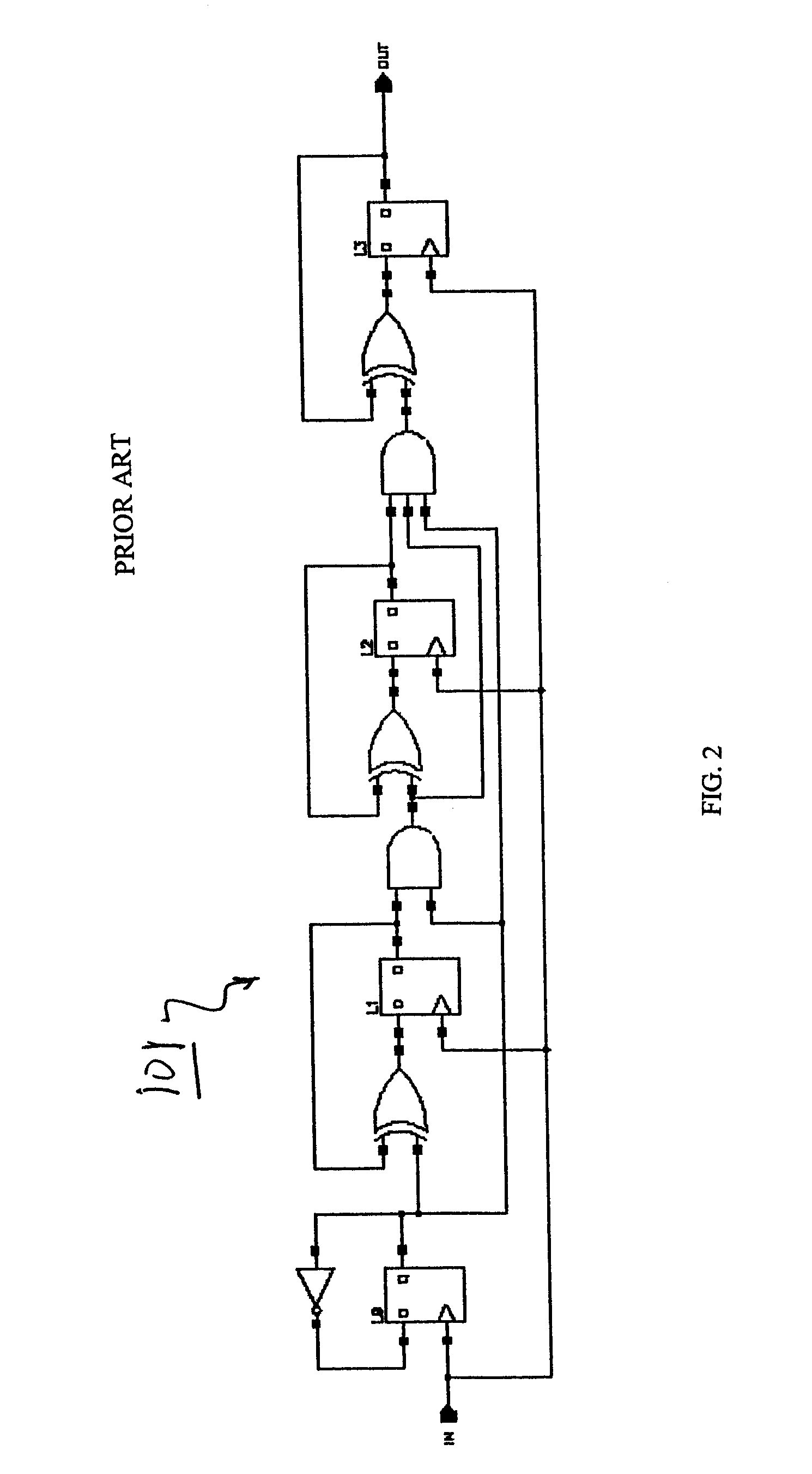
[0015]The LFSR implemented in the programmable frequency divider circuit employs a number of techniques to improve the delay of the LFSR feedback network which enhances the efficiency of the frequency divide operation. First, the feedback network is reduced by distributing the XOR functions of the feedback network across several latches, which effectively extends the function of the feedback network over multiple clock cycles. Similarly, the LFSR treats a single XOR element as a multi-stage logic function by distributing the function across more than one latch thereby extending the XOR operation over more than one clock cycle. Lastly, the odd numbered 2n−1 count of the LFSR, where n is an odd number of latches, is operated in parallel with a counter producing an even numbered (2m) output, where m is an even number of latches The respective states of the two devices are combined to form a hybrid 2m*(2n−1) counter. This approach allows a slower high-count LFSR to be replaced with a faster lower-count LFSR in parallel with a fast even numbered output counter.

Problems solved by technology

In addition, the design requires fewer logic elements in the data path compared with prior art designs, thereby consuming less physical area and dissipating less power.

Method used


Image

  • Programmable frequency divider with symmetrical output
  • Programmable frequency divider with symmetrical output
  • Programmable frequency divider with symmetrical output

Examples


third embodiment

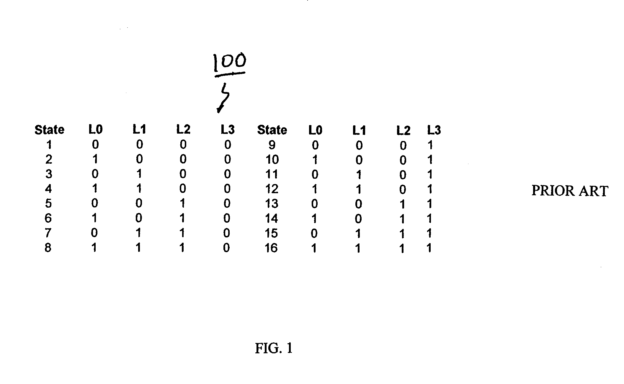
[0091]the LFSR based counter distributes a single XOR feedback network across multiple latches and therefore multiple clock cycles. The XOR element is segregated into multiple stages using standard logic gate primitives which improves latch-to-latch delay and therefore overall performance of the LFSR based counter. A four latch LFSR implementation with a single XOR feedback network is shown in FIG. 5.

[0092]FIG. 31 illustrates the technique of splitting the XOR function into a multi-stage function and distributing the logic across multiple latches. Initially, the output of the OR component 225 is fed back to the LFSR input latch L0 and the output of the NAND component 224 is fed back to latch LOB. During the next clock cycle, the outputs of latches L0 and L0B are passed through an AND gate 226 and the result is stored in Latch L1. As in the first LFSR embodiment, latch L0 will occasionally contain a known “false” value that will be corrected when this value shifts to latch L1. FIG. 3...

fourth embodiment

[0093]the high speed LFSR component of the frequency divider of the present invention combines two of the previous techniques. FIG. 33 shows a seven latch LFSR based counter coupled in parallel with a divide-by-two element and a segregated single XOR feedback network. The total number of states was reduced from 255 to 254, but the performance was improved by implementing the feedback network with a single XOR function decomposed into its component functions, which, in turn, necessitated an additional latch L0B. The final counter design has a maximum number of states that is one less than a standard eight latch design (254 versus 255) but offers a substantial improvement in performance.

fifth embodiment

[0094]the high speed LFSR counter of the frequency divider, shown in FIG. 34, adds an additional programmability feature by providing a multiplexed input to each of the LFSR latches. The LFSR counter latches can be initialized to specific values via a latch RESET input. Another latch 250 is added to control the gates of the multiplexer circuits used for programming the maximum state count.

[0095]The techniques discussed herein are not limited to a particular LFSR or symmetrical divider implementations or a specific number of dividers in parallel, but may be extended to designs with dividers of virtually any size and number with modifications that are simply a natural extension of the underlying principles.


PUM


Abstract

A programmable frequency divider circuit with symmetrical output is disclosed. The frequency divider includes a non-symmetrical LFSR based component operated in series with a symmetrical divider component. Both the LFSR and the symmetrical divider may be programmed to provide flexibility. The frequency divider can dynamically adjust the divisor of the LFSR component to overcome limitations in the divide resolution due to the series combination of dividers, providing even and odd divisor values. The divider architecture can also provide higher level functions, including synchronization of multiple divider outputs, dynamic switching of divisor values and generation of multi-phased and spaced outputs. The linear feedback shift register (LFSR) component includes a feedback logic network decomposed into multiple stages to realize a maximum latch-to-latch operational latency of one gate delay regardless of the size of the LFSR.

Description

BACKGROUND OF INVENTION[0001]1. Field of the Invention[0002]The present invention relates to the field of integrated circuit frequency dividers, particularly the realization of a symmetrical and fully programmable frequency divider using a high speed linear feedback shift register (LFSR).[0003]2. Background of the Invention[0004]In its most basic implementation, a divider circuit will accept an input signal with a given frequency and provide an output signal with a lower frequency. The relationship between the output and input signal frequencies is of the form of a programmable ratio, that is, the frequency of the output signal will be the frequency of the input signal divided by a factor N. This factor, known as the ‘divide value’ of the divider circuit, is programmable via input ‘control’ signals to the divider. These control signals are digital in nature, can assume values of ‘1’ or ‘0’, and the number of control signals will determine the number of ‘divide modes’ of the divider,...

Claims


Application Information

Patent Timeline
IPC IPC(8): G11C19/00H03K23/64H03B19/00
CPCG11C19/00
Inventor AUSTIN, JOHN S.SOBEL, MATTHEW T.
Owner MARVELL ASIA PTE LTD
Learn More