
High performance fuel processing system for fuel cell power plant

a fuel cell and processing system technology, applied in the field of fuel processing, can solve the problems of increasing the reaction rate of the ht wgs catalyst with temperature, the anode of the pem fuel cell is particularly susceptible to being “poisoned, and the reaction rate of the ht wgs catalyst is exponentially increased with temperature, so as to reduce the exothermicity, reduce the size and weight, and reduce the effect of exothermicity

Inactive Publication Date: 2005-08-23
INT FUEL CELLS
View PDF73 Cites 11 Cited by
  • Summary
  • Abstract
  • Description
  • Claims
  • Application Information

AI Technical Summary

Benefits of technology

[0017]In accordance with the invention, it has been determined that use of a high performance, low-temperature water gas shift (LT WGS) catalyst, possessing relatively lower exothermicity and being active at temperatures below 250° C., can have a significant positive impact on the fuel processing system (FPS), principally through the elimination of the high temperature, first stage, H PROX reactor 36, and also the air mixer 32 and cooler 34 associated with that reactor, and secondarily by allowing the utilization of a simpler coolant control system. Additionally, or alternatively, the use of such catalyst in the LT WGS may allow the use of a relatively smaller catalyst bed and reactor for a given requirement of CO reduction in the reformate flow. The use of such a catalyst in the LT WGS reactor enables that reactor to process the reformate to exit temperatures as low as about 250° C. and below, as governed by the thermodynamic equilibrium equation, which concomitantly permits the CO concentrations to be reduced to as low as about 2,000 ppmv, or less. With the reformate at that temperature and particularly at that CO concentration, it is then possible to eliminate the H PROX and still attain the requisite CO level of less than about 50 ppmv at the output of the L PROX.
[0018]Through use of such high-performance, low-temperature, WGS catalyst in the low-temperature water gas shift reactor, the hardware and coolant and air processing in the FPS may be simplified. Specifically, it becomes possible to eliminate the high-temperature PROX subsystem previously required. Moreover, this elimination of the H PROX subsystem allows simplification of the associated coolant and air systems, both in terms of hardware requirements and control complexity. Finally, an increase in the overall fuel cell power plant efficiency of at least 1% is achieved, since the catalyst in the H PROX would also otherwise burn hydrogen, with the amount of the efficiency increase depending upon the CO / H2 ratio and the catalyst selectivity at H PROX operating conditions.
[0019]The foregoing improvements and advantages in the design and operation of the fuel processing system include reduced system cost, volumetric reduction or minimization, and enhanced performance due to higher efficiency and improved controllability during transients. These improvements and advantages arise from the recognition that by increasing the activity of a catalyst that consists of noble metals over doped ceria to at least 0.18 moles of CO per moles of Pt per sec. (moles CO / moles equiv. Pt-sec.) at 250° C. for a gas composition of 1.5%-2.5% CO, 25%-35% H2O, 30-50% H2, 10-14% CO2, balance N2, and simultaneously decreasing the CO reaction order in the LT WGS reaction from that previously assumed with the use of commercial Cu / ZnO catalysts (˜1), the activity of a catalyst would become substantially independent of the CO partial pressure and the shift reaction could effect reduction of CO to lower concentrations and at lower temperatures. This allows reduction of CO concentration along the LT WGS reactor to levels predicted by the thermodynamic equilibrium equation with relatively smaller reactor volume than required by another catalyst of similar activity but a high CO reaction order, thus affording savings in reactor hardware costs and a reduction in system parasitic power.
[0020]In regard to the foregoing and in accordance with the invention, the catalyst employed in the LT WGS is high performance, and is capable of activity at relatively low temperatures below about 250° C. Certain noble metal-on-ceria-based, nanophase-structured catalysts are seen to provide such properties, with a preferred example being a supported platinum (Pt) and rhenium (Re) catalyst, with at least 1 wt %, preferably 1.5 to 8.0 wt %, and most preferably 2.0 to 5.0 wt %, of Pt and Re having a dispersion greater than 90% on a porous mixed metal oxide support.

Problems solved by technology

Moreover, the catalyst associated with the anode of a PEM fuel cell is particularly susceptible to being “poisoned” by carbon monoxide (CO) that may be contained in the reformate.
This reaction is exothermic (in the forward direction) and equilibrium-limited, with lower temperatures favoring higher CO conversions.
However, the reaction rate of the HT WGS catalyst increases exponentially with temperature.
Thus, there is an efficiency penalty during this process.
Moreover, since the CO reaction is highly exothermic and the levels of CO that are consumed are relatively high, the temperature in this adiabatic reactor typically increases more than 100° C. Due to the high reaction exothermicity, it may be prone to overheating, with a concomitant reverse shift reaction that converts CO2 back to CO, or to overcooling, which fails to adequately oxidize the CO.
Further, this high exothermicity of the H PROX reactor 36 can lead to unstable operation states referred to as “bifurcations”, in which the system may be seen to operate in multiple “steady states”.
This is due to the coupling effects in the changes of the O2 / CO ratio and the coolant flow rates during operation of the system in a transient mode, and leads to either serious overheating, i. e., temperature runaway, or to overcooling, i. e., process extinguishing.
As in the examples described above, these modes may be mitigated only with the use of sophisticated, and therefore expensive, coolant and air control systems.

Method used


Image

  • High performance fuel processing system for fuel cell power plant
  • High performance fuel processing system for fuel cell power plant
  • High performance fuel processing system for fuel cell power plant

Examples


Embodiment Construction

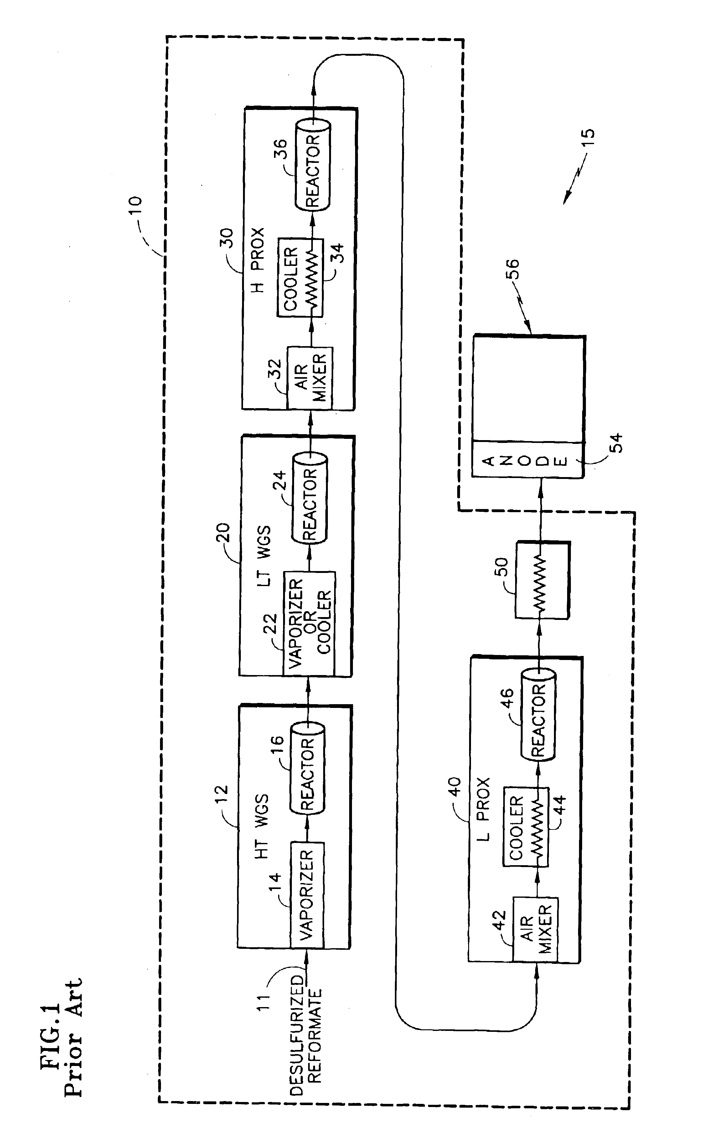
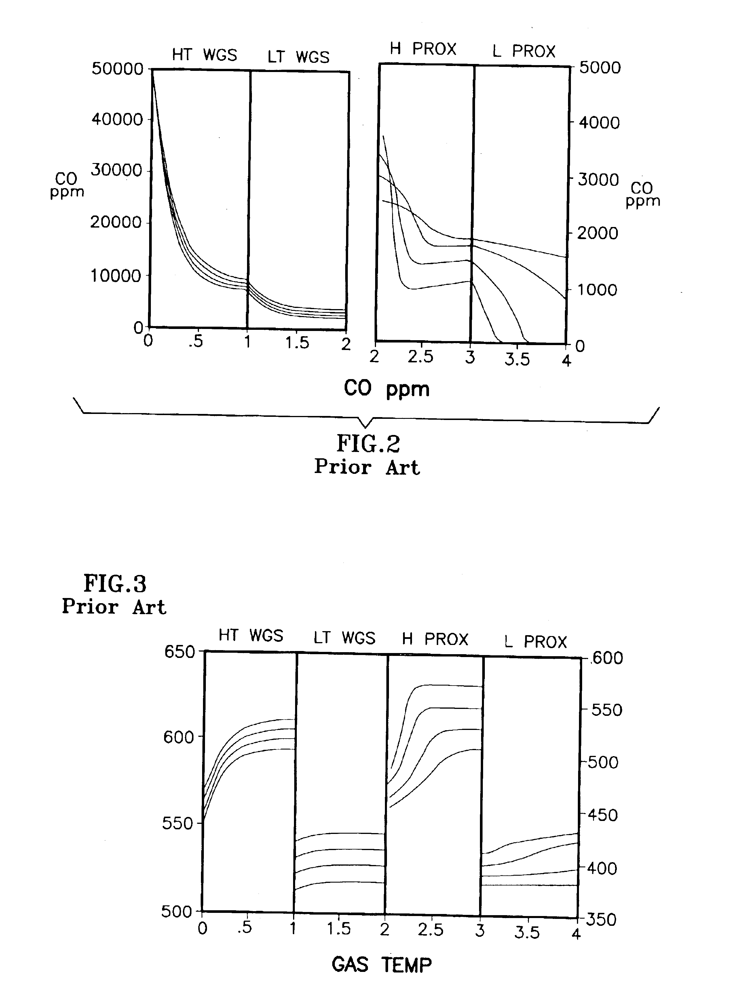
[0032]The description of the prior art, with reference to FIGS. 1-4, revealed the limitations and / or sensitivities of existing FPS configurations, particularly in their requirement for both an H PROX subsystem 30 and an L PROX subsystem 40, and the further complex dependence on coolant flow for CO conversion at differing power conditions. This configuration assumed the use of a recently-developed, noble metal-based, WGS catalyst of the general type described in U.S. Pat. No. 6,455,182 for Shift Converter Having an Improved Catalyst Composition, and Method for its Use, assigned to the assignee of the present invention, in at least the LT WGS reactor 24, which catalyst typically has a high activity. The activation energy and CO reaction order for such catalyst might typically be 14 to 20 Kcal / mole of CO and 0.20 to 0.50 respectively. Similarly, the temperature of the reformate exiting from the LT WGS reactor 24 might be between 280° and 320° C. and the CO level from 10,000 to 5,000 pp...


PUM

PropertyMeasurementUnit
Temperatureaaaaaaaaaa
Sizeaaaaaaaaaa
Sizeaaaaaaaaaa

Abstract

A fuel processing system (FPS) (110) is provided for a fuel cell power plant (115) having a fuel cell stack assembly (CSA) (56). A water gas shift (WGS) reaction section (12, 120) of the FPS (110) reduces the concentration of carbon monoxide (CO) in the supplied hydrocarbon reformate, and a preferred oxidation (PROX) section (40) further reduces the CO concentration to an acceptable level. The WGS section (12, 120) includes a reactor (124) with a high activity catalyst for reducing the reformate Co concentration to a relatively low level, e.g., 2,000 ppmv or less, thereby relatively reducing the structural volume of the FPS (110). The high activity catalyst is active at temperatures as low as 250° C., and may be a noble-metal-on-ceria catalyst of Pt and Re on a nanocrystaline, cerium oxide-based support. Then only a low temperature PROX reactor (46) is required for preferential oxidation in the FPS (110).

Description

TECHNICAL FIELD[0001]This invention relates to fuel processing and more particularly to processing fuel for use with fuel cells. More particularly still, the invention relates to a fuel processing system for use with low operating temperature fuel cell power plants, such as a PEM fuel cell.BACKGROUND ART[0002]Fuel cell power plants are used increasingly to provide electrical power for a variety of end uses. The fuel cell power plant typically includes one or more fuel cell stack assemblies (CSA), each consisting of an anode, a cathode, and an electrolyte that separates the anode and cathode. Fuel reactant (for a PEM fuel cell), which is typically a hydrogen-rich stream, enters the anode of the CSA, and an oxidant reactant, typically air, enters the cathode. A catalyst in the anode causes the hydrogen to oxidize, resulting in the creation of hydrogen ions, which pass through the electrolyte to the cathode to create the electrical current of the power plant. In addition to the CSA, th...

Claims


Application Information

Patent Timeline
IPC IPC(8): B01D53/62B01J23/54B01J23/63C01B3/00C01B3/48H01M8/10H01M8/06B01JC01B3/16C01B3/58
CPCC01B3/16C01B3/583H01M8/0612H01M8/0668C01B2203/0233C01B2203/0244C01B2203/0288C01B2203/044C01B2203/047C01B2203/066C01B2203/1041C01B2203/107C01B2203/127Y02E60/50Y02P20/52
Inventor DARDAS, ZISSISVANDERSPURT, THOMAS HENRYGUPTA, NIKUNJGHOSH, SHUBHROSHE, YING
Owner INT FUEL CELLS
Learn More