
Polystyrene as a resist for making patterned media

a technology of polystyrene and resist, which is applied in the field of patterned magnetic media, can solve the problems of poor ion stopping effectiveness, reduced thickness, and implantation on the magnetic properties of the magnetic layer, and achieve excellent ion stopping properties, reduce coercivity (hc), and reduce mr

Inactive Publication Date: 2005-01-04
SEAGATE TECH LLC
View PDF6 Cites 15 Cited by
  • Summary
  • Abstract
  • Description
  • Claims
  • Application Information

AI Technical Summary

Benefits of technology

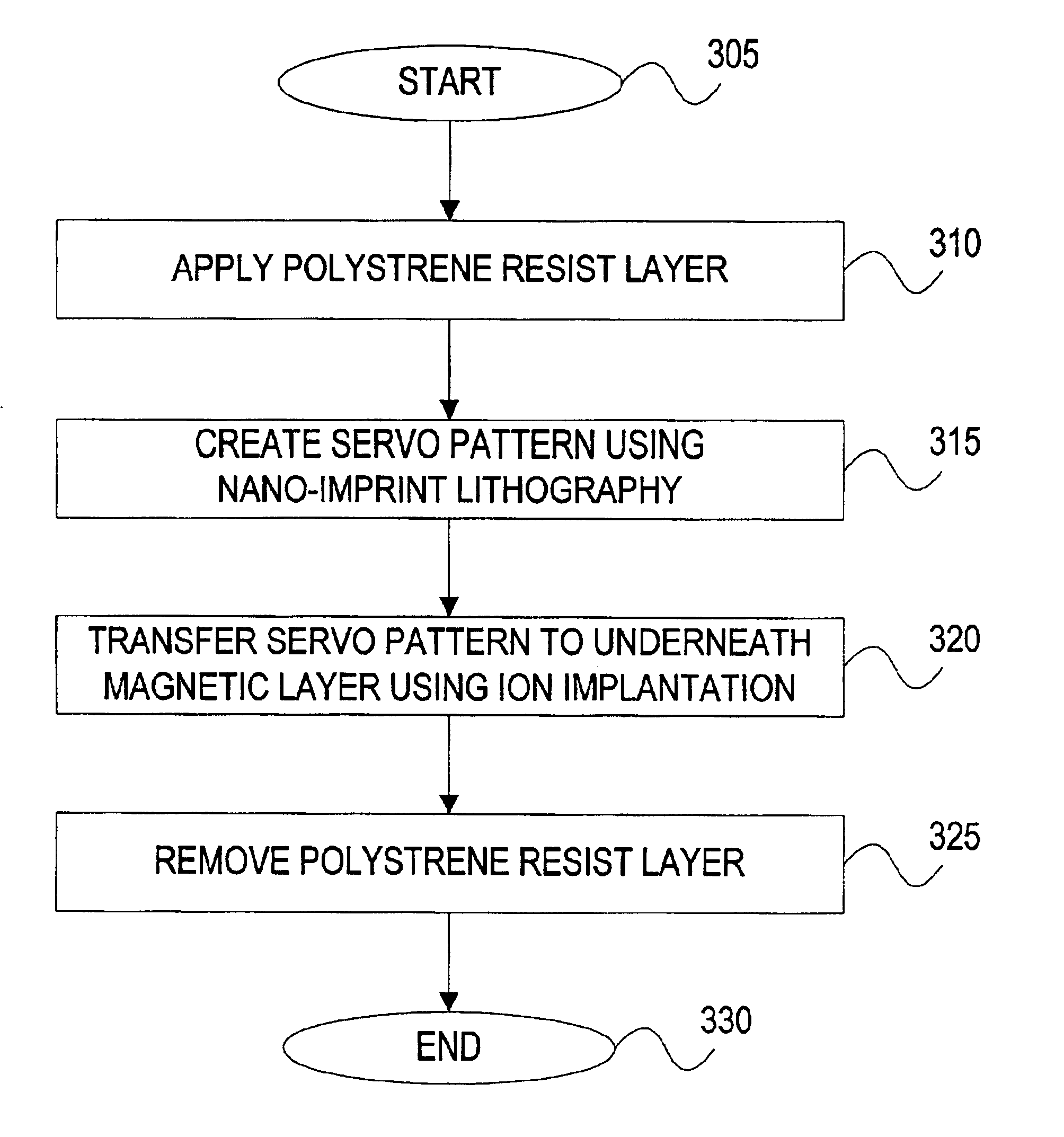
Polystyrene, which is deposited over a magnetic media, is first stamped with a stamper that creates a nano-imprint pattern on the polystyrene. The pattern consists of thinner and thicker regions of polystyrene, which are the negative image of the stamp pattern, over the magnetic media. The patterned structure is then exposed to ions. Since polystyrene has excellent ion stopping properties, the thicker polystyrene stops the incoming ions. However, the thinner portions of the stamped polystyrene surface is incapable of stopping the incoming ions because it is too thin and consequently allows the ions to pass through to the magnetic layer. Since the ions penetrate through the polystyrene layer and the protective layer to the magnetic layer according to the stamped pattern, the same stamped pattern is reproduced on the magnetic layer in the form of reduced coercivity (Hc) and reduced Mrt.

Problems solved by technology

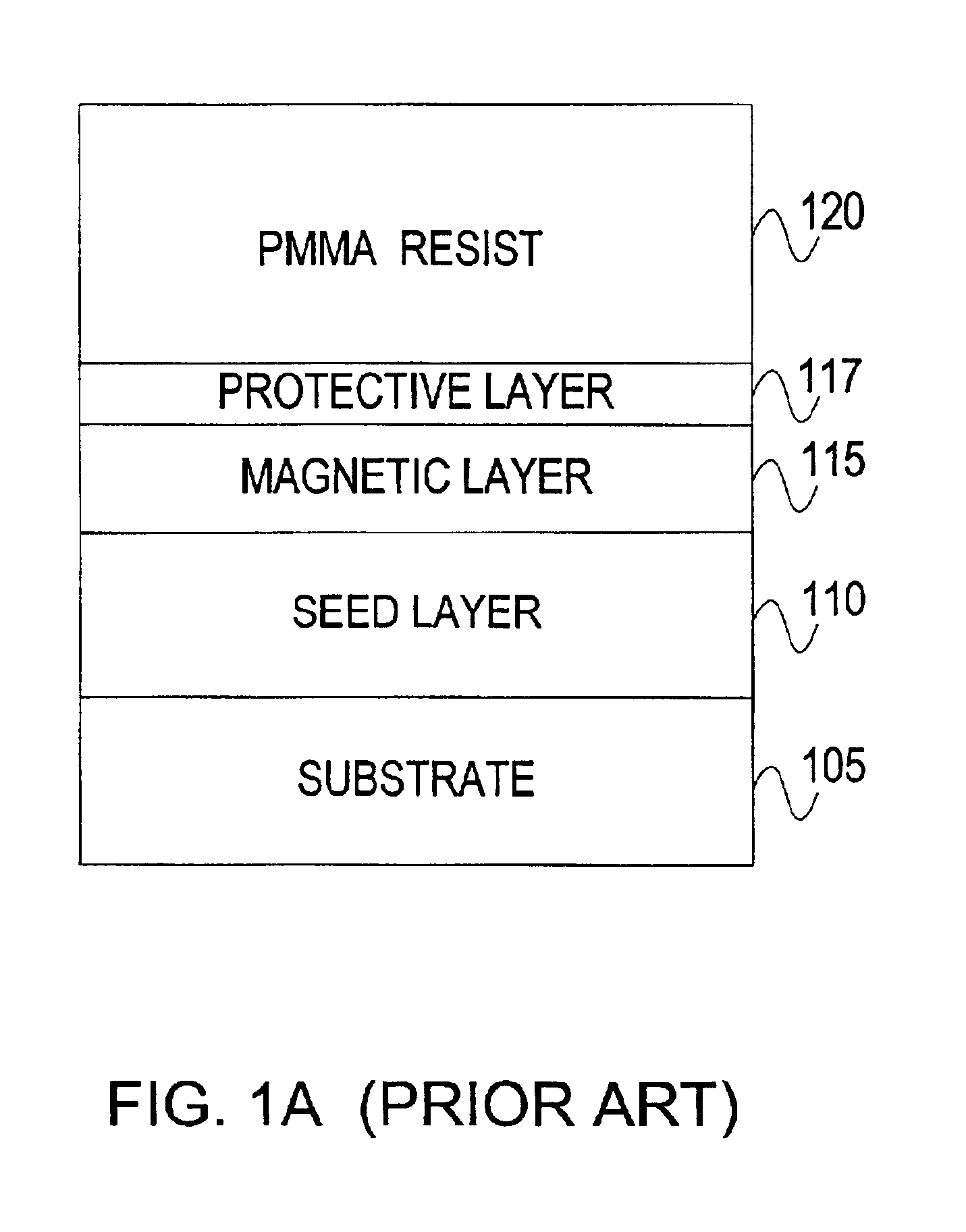
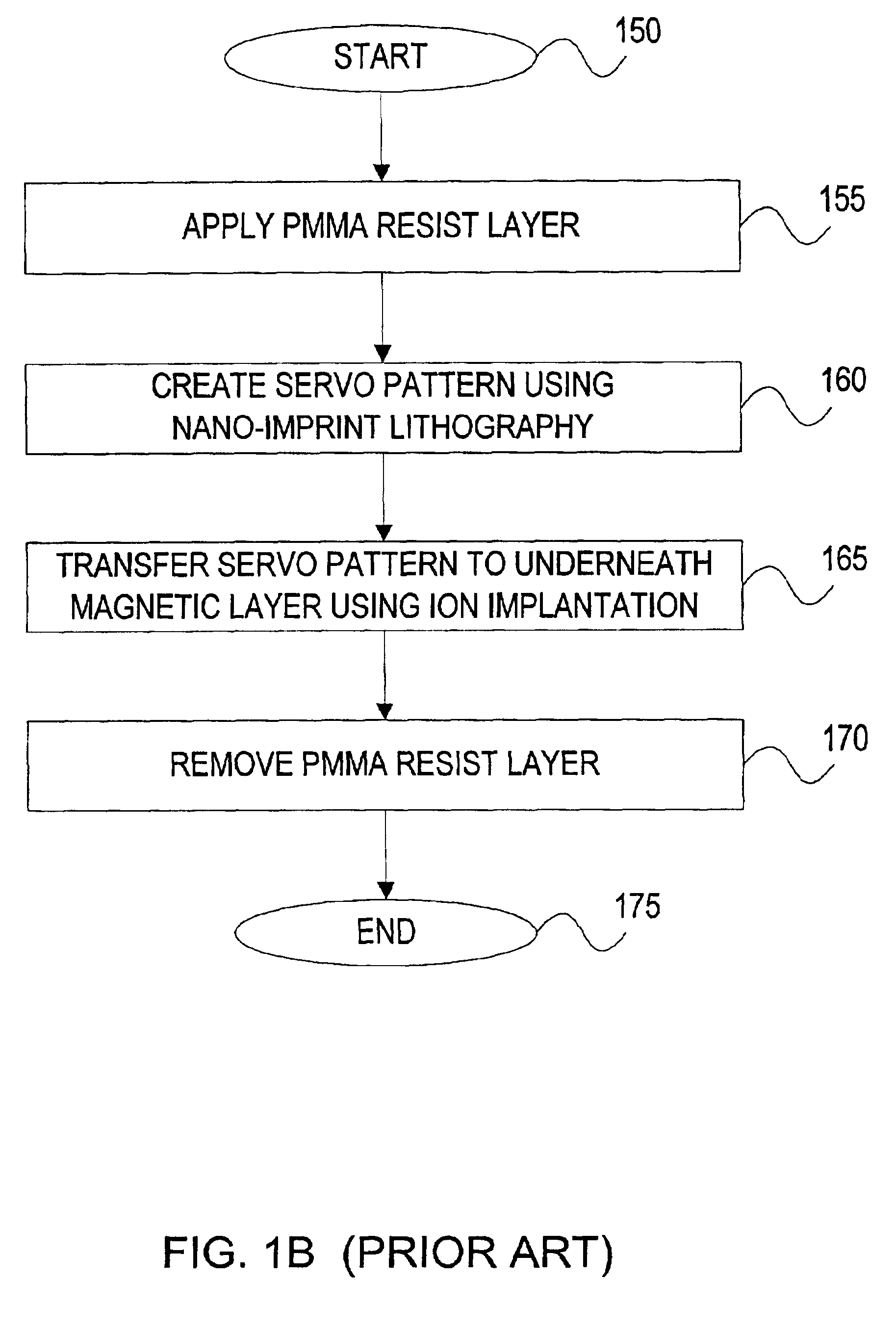
The poor ion stopping effectiveness of the PMMA resist 120 along with its reduction in thickness when exposed to ions is the cause for the damage that ion implantation has on the magnetic properties of the magnetic layer.

Method used


Image

  • Polystyrene as a resist for making patterned media
  • Polystyrene as a resist for making patterned media
  • Polystyrene as a resist for making patterned media

Examples


Embodiment Construction

The invention provides a system and method for nano-imprint lithography and subsequent ion implantation for servo pattern media.

FIG. 2 is a block diagram showing a magnetic medium, ready for patterning, having a substrate 105, a seed layer 110, a magnetic layer 115, a protective layer 117 and a polystyrene resist layer 210. Polystyrene resist layer 210 overlays the protective layer 117 in accordance with one embodiment of the invention. Although the preferred embodiment is described using polystyrene as the thermoplastic resist material, the invention is not limited to polystyrene. Other forms of polymers, can any styrene co-polymers, can also be used as a thermoplastic resist material. The resist materials used in the preferred embodiment all have thermoplastic properties.

Although, the preferred embodiment of FIG. 2 shows the seed layer 110 deposited between the substrate 105 and the magnetic layer 115 the invention is not dependent on the presence of the seed layer 110. Since the ...


PUM

PropertyMeasurementUnit
temperaturesaaaaaaaaaa
thermoplasticaaaaaaaaaa

Abstract

A system and method for forming servo patterns on magnetic media is disclosed. A magnetic film coated with a layer of polystyrene is stamped with a nickel stamper reproducing the negative image of the stamped pattern on the polystyrene. Ions are then accelerated towards the surface of the polystyrene, which stopps the ions in the areas where the polystyrene is thick and allows the ions to penetrate through to the magnetic layer in the areas where the polystyrene is thin. The ions, which penetrate through to the magnetic layer, interact with the magnetic layer altering the magnetic layer's structure reducing its coercivity (Hc) and remnant moment (Mrt). This reproduces the stamped polystyrene pattern on the magnetic layer. The polystyrene is then removed by oxygen plasma etching the surface leaving behind a patterned magnetic media.

Description

BACKGROUND OF THE INVENTION1. Field of the InventionThe present invention relates generally to patterned magnetic media, and more particularly to resist used for nano-imprint lithography and subsequent ion implantation in patterned magnetic media.2. Description of the Related ArtIn the microelectronics industry, a conventional patterning process usually consists of two parts. The first part includes patterning a polymeric resist layer by lithographic methods, such as photolithography, e-beam or X-ray lithography, for mask definition. The second part includes subsequently transferring the pattern into a hard material using a process such as dry etching, wet etching, lift-off, or electroforming. As the feature size approaches sub-100 nm, there is an urgent need for fast reliable and cost effective nano-lithography. Nano-imprint lithography, developed in recent years has shown promise in meeting this need. Nano-imprint lithography creates pattern in a thermoplastic resist layer by hot ...

Claims


Application Information

Patent Timeline
Patent Type & Authority Patents(United States)
IPC IPC(8): G03F7/00G11B5/855G11B5/74G11B5/82
CPCB82Y10/00B82Y40/00G03F7/0002G11B5/743G11B5/855G11B5/74G11B5/732Y10S428/90G11B5/82G11B5/7379Y10T428/31678Y10T428/249921
Inventor WANG, HONGYINGDEEMAN, NEILWAGO, KOICHIKURATAKA, NOBUO
Owner SEAGATE TECH LLC
Learn More