Magnetic recording medium and magnetic storage apparatus
a recording medium and magnetic storage technology, applied in the field of magnetic recording medium and magnetic storage apparatus, can solve the problem of reducing the magnetic anisotropy constant ku
- Summary
- Abstract
- Description
- Claims
- Application Information
AI Technical Summary
Benefits of technology
Problems solved by technology
Method used
Image
Examples
first embodiment
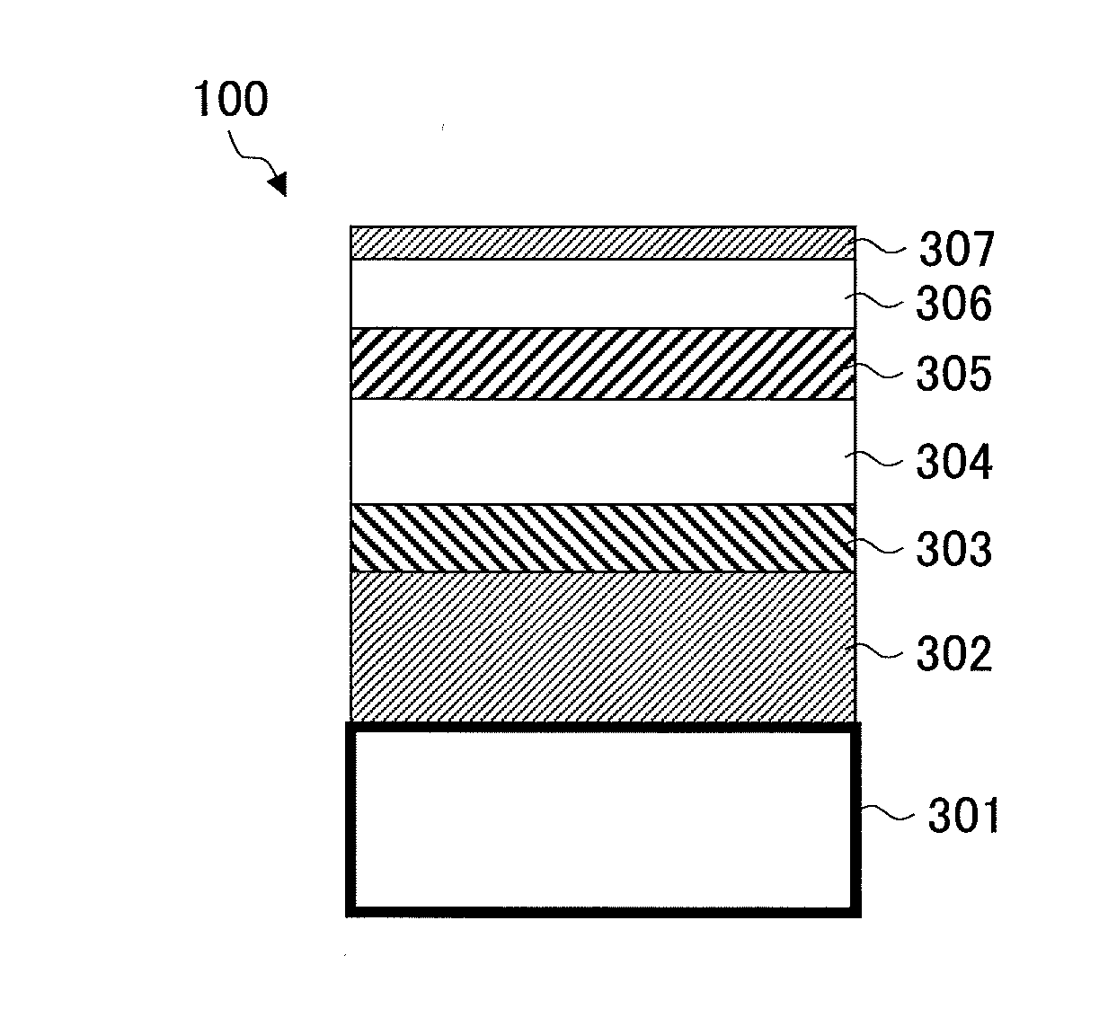
[0025]An example of a configuration of a magnetic recording medium 100 according to a first embodiment of the present invention is described.
[0026]The magnetic recording medium 100 according to an embodiment of the present invention includes a substrate. The magnetic recording medium 100 also includes multiple underlayers and a magnetic layer that are formed on the substrate. The main component of the magnetic layer is an alloy having an L10 structure. At least one of the multiple underlayers is a crystalline underlayer containing W (tungsten).
[0027]The main component of the crystalline underlayer is W. In addition, the crystalline underlayer containing W includes 1 mol % or more to 20 mol % or less of one or more kinds of elements selected from B, Si, and C. Alternatively, the crystalline underlayer includes 1 vol % or more to 50 vol % or less of an oxide.
[0028]Further, a barrier layer is formed between the crystalline underlayer containing W and the magnetic layer. The barrier lay...
second embodiment
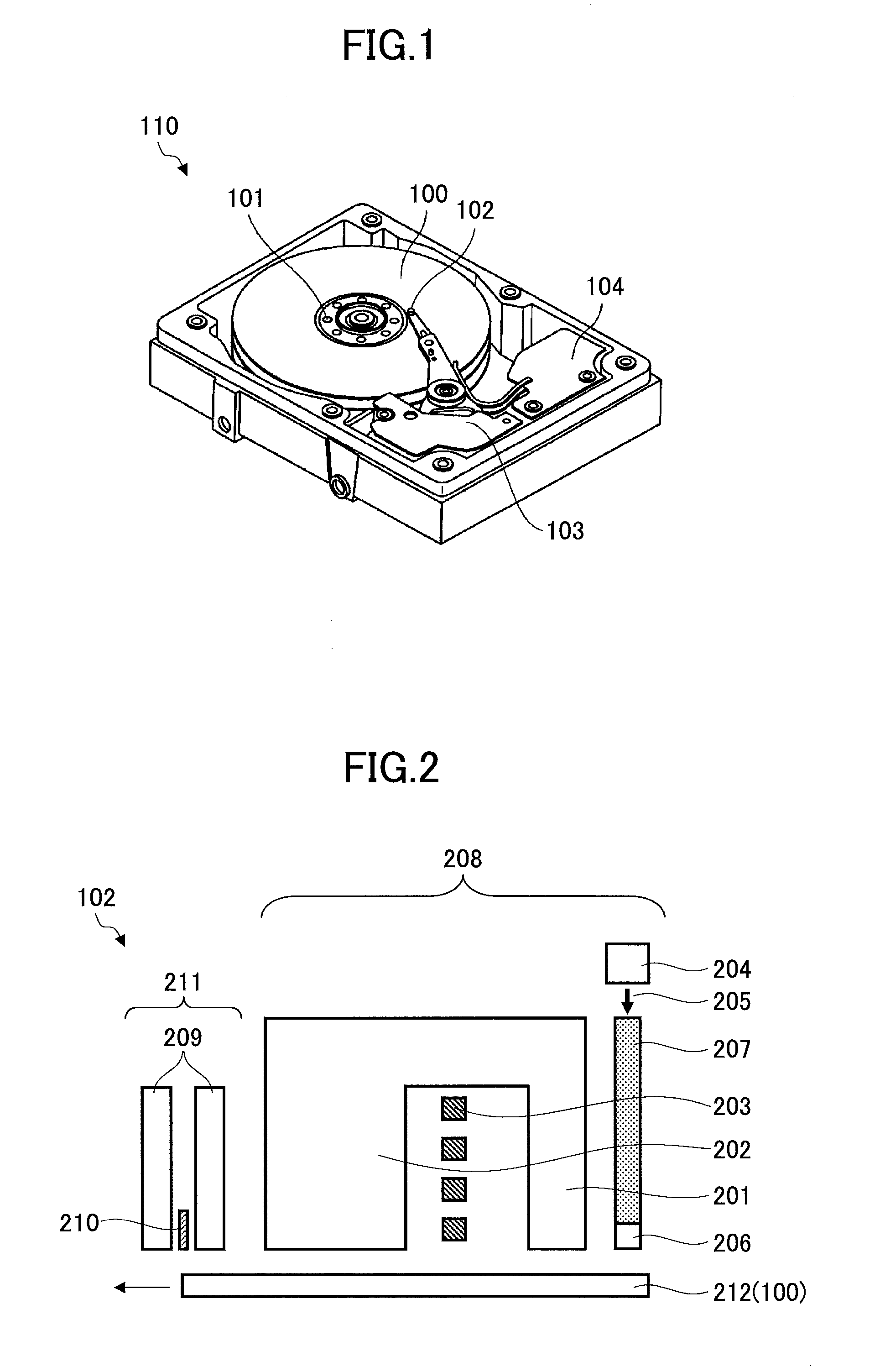
[0061]Next, an example of a configuration of a magnetic storage apparatus 110 according to a second embodiment of the present invention is described. Although this embodiment illustrates an example of a thermally assisted magnetic recording type magnetic storage apparatus, the magnetic storage apparatus may also be a microwave assisted magnetic recording type magnetic storage apparatus.
[0062]The magnetic storage apparatus 110 of this embodiment includes the above-described magnetic recording medium 100 of the first embodiment.
[0063]As described in detail below, the magnetic storage apparatus 110 includes, for example, a magnetic recording medium drive part for rotating the magnetic recording medium 100 and a magnetic head having a near-field light generating element provided on a distal end of the magnetic head. The magnetic storage apparatus 110 also includes a laser generating part for heating the magnetic recording medium 100, an optical waveguide for guiding a laser beam radiate...
first experimental example
Practical Examples 1-1 to 1-13, Comparative Examples 1-1 to 1-2
[0069]In the first experimental example, samples of the practical examples 1-1 to 1-13 and samples of comparative examples 1-1 to 1-2 are fabricated and evaluated.
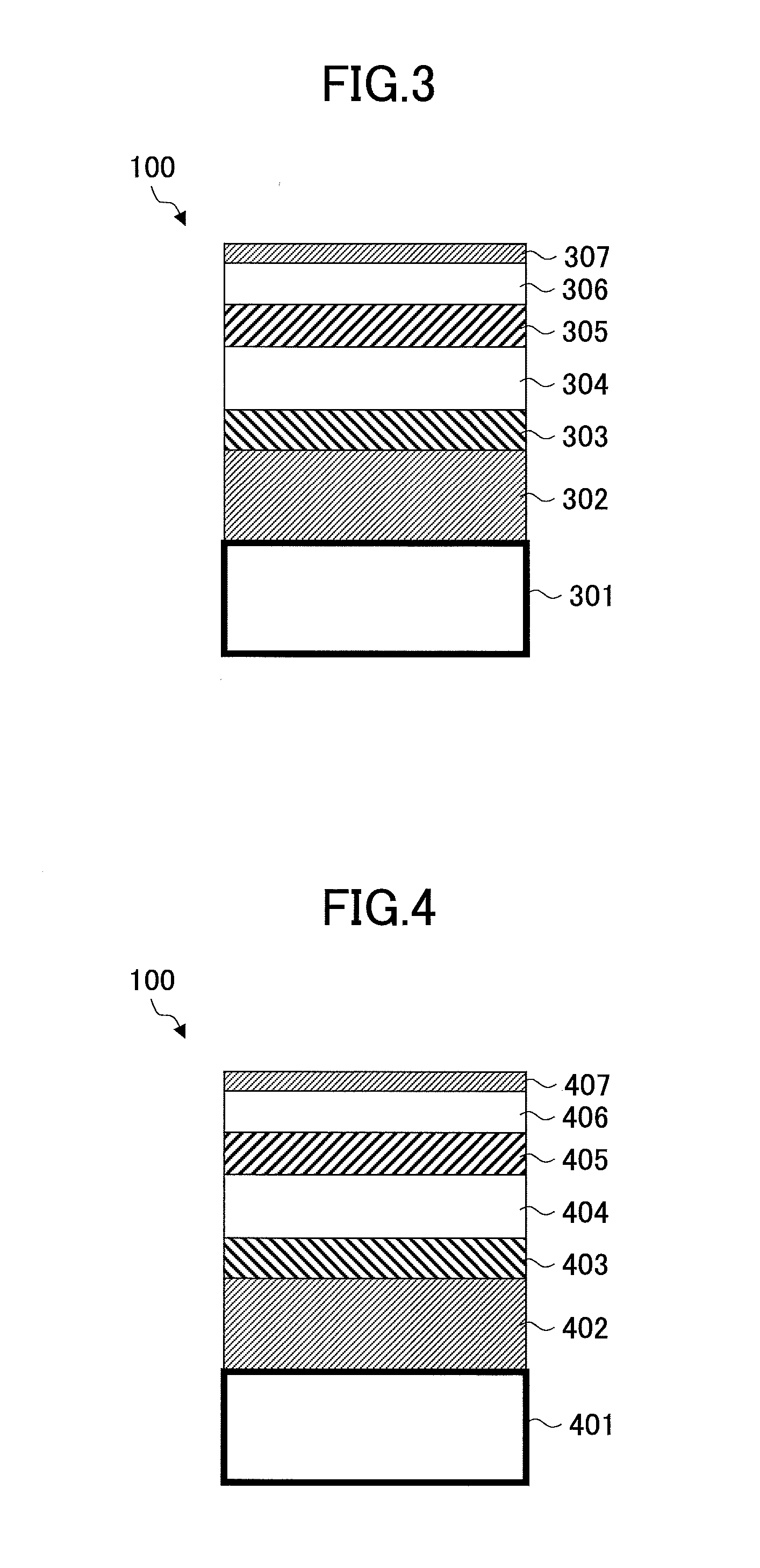
[0070]FIG. 3 is a schematic diagram illustrating a cross section of a layer configuration of a magnetic recording medium that is fabricated in the first experimental example. The processes of fabricating the magnetic recording medium is described below.
[0071]In the first experimental example, a seed layer 302 is formed on a glass substrate 301. The size of the glass substrate is 2.5 inches. A Ni-35 at % Ta layer having a film thickness of 25 nm is formed as the seed layer 302. Then, the glass substrate 301 is heated at a temperature of 300° C.
[0072]Then, an orientation control underlayer 303 is formed. A Ru-50 at % Al layer having a film thickness of 20 nm is formed as the orientation control underlayer 303.
[0073]Then, a crystalline underlayer 304 containing W ...
PUM
| Property | Measurement | Unit |
|---|---|---|
| magnetic particle diameter | aaaaa | aaaaa |
| magnetic particle diameter | aaaaa | aaaaa |
| magnetic | aaaaa | aaaaa |
Abstract
Description
Claims
Application Information
 - R&D
- Intellectual Property
- Life Sciences
- Materials
- Tech Scout
- Unparalleled Data Quality
- Higher Quality Content
- 60% Fewer Hallucinations
Browse by: Latest US Patents, China's latest patents, Technical Efficacy Thesaurus, Application Domain, Technology Topic, Popular Technical Reports.
© 2025 PatSnap. All rights reserved.Legal|Privacy policy|Modern Slavery Act Transparency Statement|Sitemap|About US| Contact US: help@patsnap.com


