
Opto-magnetic recording medium with a garnet ferrite recording layer, and opto-magnetic information recording/reproducing device

a technology of opto-magnetic information and recording medium, which is applied in the field of magnetooptical recording medium, can solve the problems of garnet ferrite layer internal stress, thin metal layer prone to deterioration, cracks in garnet ferrite layer,

Inactive Publication Date: 2004-07-06
CENT NAT DE LA RECHERCHE SCI +1
View PDF24 Cites 16 Cited by
  • Summary
  • Abstract
  • Description
  • Claims
  • Application Information

AI Technical Summary

Benefits of technology

It is another object of the present invention to produce a new magneto-optical recording and playback device that is suitable for data recording and playback on such a magneto-optical recording medium and is able to increase the S / N and C / N ratios.
For example, if the light absorption rate of the magneto-optical recording medium is high for light with a short wavelength, efficient data recording and reduction of the power of the light beam for data recording are possible by shortening the wavelength of the light beam for data recording. On the other hand, if the light absorption rate of the magneto-optical recording medium is low for light with a long wavelength, reducing undesirable heating of a recording layer is possible by lengthening the wavelength of the light beam for data reading, and increasing of C / N ratio is possible because a reflected light beam with high power can be obtained.

Problems solved by technology

However, the thin metal layer is prone to deterioration due to oxidation and other factors.
In the case in which garnet ferrite is used as the material for magneto-optical recording, however, internal stress occurs in a garnet ferrite layer when spattering for formation of the layer on a substrate.
This sometimes results in cracks in the garnet ferrite layer, rough morphology of the surface of the layer and very large crystal particles, which are not preferable because they cause the problem of medium noise when recording and playing back.
However, it is said that metal materials such as the above amorphous alloy are not suitable for multi-layered structures since they have a relatively small Kerr Effect and a high absorption coefficient.
However, a multi-layered recording medium having a recording layer made from bismuth-substituted garnet ferrite requires a high power light beam when writing data because the absorption coefficient of the recording layer is small.
Accordingly, the manufacturing process shown in Japanese Patent Publication No. 6-282868 becomes complex because formation of the light absorption layer and the protective layer is necessary in addition to formation of the recording layer, which leads to increased production costs.
Besides, properties such as the S / N ratio of the magneto-optical recording medium manufactured by the above method have not yet reached a satisfactory level.
However, the above method is impractical because the manufacturing process is complex.
Therefore, compositional deviations occur in the direction perpendicular to the layer surface in the multi-layered structure, which causes the problem of deterioration of properties such as the S / N ratio and repeatability.
Furthermore, high density recording is hindered if the above mentioned method is employed because it is impossible for the above mentioned garnet ferrite layer formation method to provide minute crystals on the order of nanometers.
However, even in this system, the S / N and C / N ratios have not yet reached a satisfactory level.
Besides, this system lacks generality because it is not suitable for a magneto-optical recording medium that has a relatively thick protective layer, which is, for example, disclosed in Japanese Patent Publication No.
Nevertheless, there is the problem that sufficient signal output cannot be obtained since the absorption coefficient of the spinel ferrite layer itself is large.

Method used


Image

  • Opto-magnetic recording medium with a garnet ferrite recording layer, and opto-magnetic information recording/reproducing device
  • Opto-magnetic recording medium with a garnet ferrite recording layer, and opto-magnetic information recording/reproducing device
  • Opto-magnetic recording medium with a garnet ferrite recording layer, and opto-magnetic information recording/reproducing device

Examples


embodiments 1 and 2

[Embodiments 1 and 2]

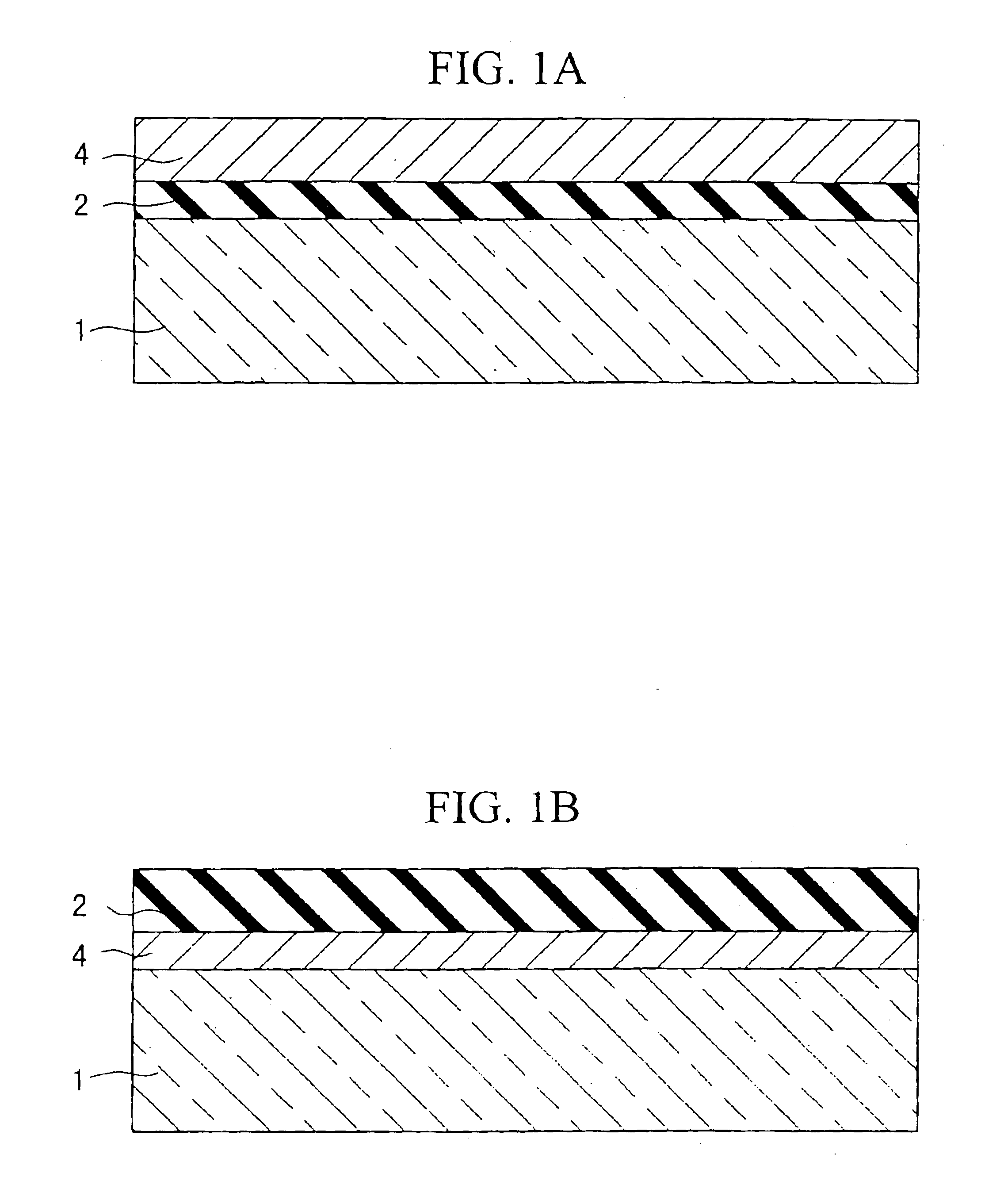
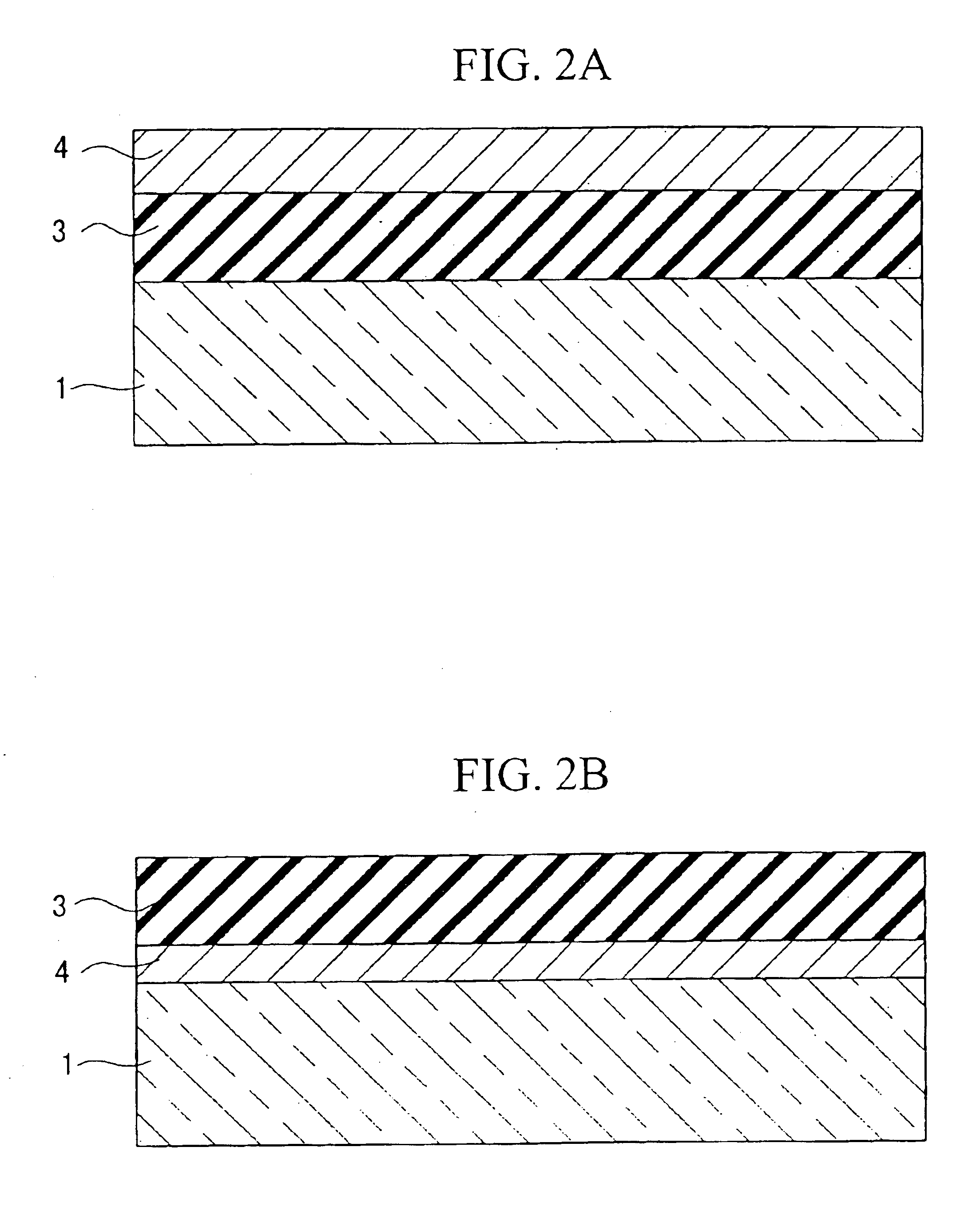
FIG. 3 shows two types of section structure of a magneto-optical recording medium having a recording layer which consists of two layers of garnet ferrite / spinel ferrite (or rutile)(hereunder, referred to as "Embodiment 1") or of two layers of garnet ferrite / hematite (hereunder, referred to as "Embodiment 2"). In the case shown in FIG. 3(a), the garnet ferrite layer 3 is layered on the spinel ferrite (or rutile or hematite) layer 2 formed on the quartz glass substrate 1, and the garnet ferrite layer 3 is covered with the metal reflective layer 4. On the other hand, the case shown in FIG. 3(b) is different from the case of FIG. 3(a) in a point that the spinel ferrite(or rutile or hematite) layer 2 and the garnet ferrite layer 3 are layered on the metal reflective layer 4 formed on the quartz glass substrate 1. Incidentally, recording and playback are executed by irradiation of a laser from the bottom and through the quartz glass substrate 1 in the case of FIG. 3(a...

embodiment 3

by the same method used for Embodiments 1 and 2, except that heat treatment for the multiple recording layer 5, which was previously formed by layering a plurality of spinel ferrite (or rutile or hematite) layers and garnet ferrite layers, was performed only once. The layer structure type shown in FIG. 6(a) and that shown in FIG. 6(b) correspond to the case shown in FIG. 3(a) of Embodiment 1 or 2 and the case shown in FIG. 3(b) of Embodiment 1 or 2, respectively.

According to observation of the magnetic properties of Embodiment 3, when either spinel ferrite or rutile, but not garnet ferrite, was selected as the material of the multiple recording layer 5, it had 20000 e of magnet coercive force, 13 emu / cc of saturation magnetization and 10 emu / cc of residual magnetization, and the square ratio was about 0.8, and these values were the same as those of Embodiment 1. Besides, the surface roughness and the crystal particle diameter of the multiple recording layer 5 after heat-treatment we...

embodiment 4

[Embodiment 4]

FIG. 7 shows two types of section structure of a magneto-optical recording medium having a recording layer which consists of two layers of garnet ferrite / spinel ferrite (or rutile or hematite), and grooves for servo control on its surface (hereunder, referred to as "Embodiment 4"). In the case shown in FIG. 7(a), the garnet ferrite layer 3 is layered on the spinel ferrite (or rutile or hematite) layer 2 formed on the quartz glass layer 1, and the garnet ferrite layer 3 is covered with the metal reflective layer 4. On the other hand, the case shown in FIG. 7(b) is different from that of FIG. 7(a) in that the spinel ferrite(or rutile or hematite) layer 2 is layered on the metal reflective layer 4 formed on the quartz glass substrate 1.

As shown in the Figure, in Embodiment 4, the grooves 6 are formed on the surface of the spinel ferrite (or rutile or hematite) layer 2, the garnet ferrite layer 3 and the metal reflective layer 4 by employing a quartz glass substrate 1 havi...


PUM

PropertyMeasurementUnit
thicknessaaaaaaaaaa
thicknessaaaaaaaaaa
thicknessaaaaaaaaaa

Abstract

This invention relates to magneto-optical recording media such as magneto-optical disks and cards, manufacturing methods of the medium and a magneto-optical recording and playback device to record and play back data using the magneto-optical recording media. The magneto-optical recording medium of the present invention has a recording layer and a reflective layer on a substrate, and the recording layer has a layered structure in which at least one spinel ferrite (or rutile-type oxide or hematite) layer and at least one garnet ferrite layer are piled together. It is preferable that the layered structure is formed on tracks where data are recorded. The manufacturing method of the present invention comprises the steps of heat treatment in the range of 500-700° C., preferably 600-630° C., after the formation of the recording layer. In the magneto-optical recording and playback device to record and play back data of the present invention, the wavelength of light for recording data is different from that for reading data, which is preferable for a magneto-optical recording medium comprising a garnet ferrite layer.

Description

1. Field of the InventionThis invention relates to a magneto-optical recording medium such as magneto-optical disk and card, a manufacturing method for the medium and a magneto-optical recording and playback device to record and play back data using the magneto-optical recording medium. This invention specially relates to a magneto-optical recording medium having a recording layer comprising a garnet ferrite layer and being ideal for high density and proximity recording, a manufacturing method for the medium and a magneto-optical recording and playback device for the medium.2. Background ArtIn conventional magneto-optical recording media on the market, the recording layer is mainly made from a thin metal layer. Data are recorded onto the recording layer as recorded bits by changing the optical properties such as the transmission or reflection rate of minute spots on the recording layer by a light beam for recording data. An amorphous alloy of rare earth metals such as TbFeCo is a ty...

Claims


Application Information

Patent Timeline
Patent Type & Authority Patents(United States)
IPC IPC(8): G11B11/105G11B11/00
CPCG11B7/1275G11B11/10536G11B11/10543G11B11/10582G11B11/10584G11B11/10586Y10T428/2457Y10T428/24479Y10T428/31Y10T428/12646Y10T428/263Y10T428/12931Y10T428/12465Y10T428/12667Y10T428/24967G11B11/10532
Inventor FURUYA, AKINORIYOSHIKAWA, HIROSHITANABE, TAKAYAYAMAMOTO, MANABUOHKUBO, TOSHIFUMIBOUET, LAURENCETAILHADES, PHILIPPEDESPAX, CORINEROUSSET, ABEL
Owner CENT NAT DE LA RECHERCHE SCI
Learn More