Method and apparatus for producing carbon dioxide

Inactive Publication Date: 2003-03-25
PRAXAIR TECH INC
View PDF11 Cites 59 Cited by
  • Summary
  • Abstract
  • Description
  • Claims
  • Application Information

AI Technical Summary

Benefits of technology

A portion of a first retentate portion of the first process gas may be flowed along a cathode side of a second membrane, having opposite second cathode and anode sides, that is at operating conditions effective to transport a second permeate oxygen portion from the second cathode side to the second anode side. A product gas may be recovered from a second retentate portion. The product gas may be selected from the group consisting of nitrogen, argon, and mixtures thereof. A second reactive purge gas may be flowed along the second anode side. The second purge gas may contain a low grade fuel gas and diluent gases selected from the group consisting of steam and a remainder of the second retentate portion. The second reactive purge gas may be reacted with the second permeate oxygen portion in a complete or partial oxidation reaction. A product of the partial oxidation reaction may be flowed along the first anode side. The second reactive purge gas may be natural gas and syngas may be recovered as a product of the partial oxidation reaction. One of the advantages of the arrangement is that the second stage may be operated under fuel rich conditions to assure more complete removal of oxygen from the second retentate stream.
The advantage of multistage arrangements with interstage retentate cooling is that it permits removal of essentially all of the oxygen from an air stream without need for additional internal reactor cooling. The three reactors 30A-30C need not all be of the same size. For example, the three reactors could be arranged from a smallest 30A to a largest 30C so that the amount of oxygen transported across each reactor and the amount of heat generated in each reactor would be approximately equal for all three reactors. In general countercurrent or cross-countercurrent flow between retentate and anode side fluids is preferred in all reactors to maximize the driving force for oxygen transport.

Problems solved by technology

Although the potential for these oxide ceramic materials as gas separation membranes is great, there are certain problems in their use.
The most obvious difficulty is that all of the known oxide ceramic materials exhibit appreciable oxygen ion conductivity only at elevated temperatures.
This limitation remains despite much research to find materials that work well at lower temperatures.
The latter problem is aggravated by ion transport membrane operating temperatures being in the range from 800.degree. C. to 1100.degree. C.
Mazanec et al., however, does not address issues related to integrating such systems with oxygen production from gas turbine cycles, heat management to maintain membrane surfaces at the desired uniform temperatures, flow dynamics to achieve effective mass transfer, or the need for balancing reaction kinetics with oxygen ion conductivity to maintain the appropriate oxygen partial pressure for materials stability.
'359 patent has the disadvantage that the feed gas stream to the ion transport separator contains products of combustion which dilute the ion transport separator feed gas stream, reduce the oxygen driving force, and could act as an adverse contaminant to some mixed conductor materials.
The alternative configuration has the disadvantage of requiring an additional, potentially expensive, heat exchanger.
Either method could also have a problem maintaining stable combustion in the first combustor since the fuel-to-air equivalence ratio will be low, especially where the heat contained in the turbine exhaust is regeneratively recovered by the feed air gas stream and the heat duty of the first combustor is small.
In this process, the type of fuel is generally limited to "clean" fuels such as natural gas, oils, or synthesis gas.

Method used


Image

  • Method and apparatus for producing carbon dioxide
  • Method and apparatus for producing carbon dioxide
  • Method and apparatus for producing carbon dioxide

Examples


example 1

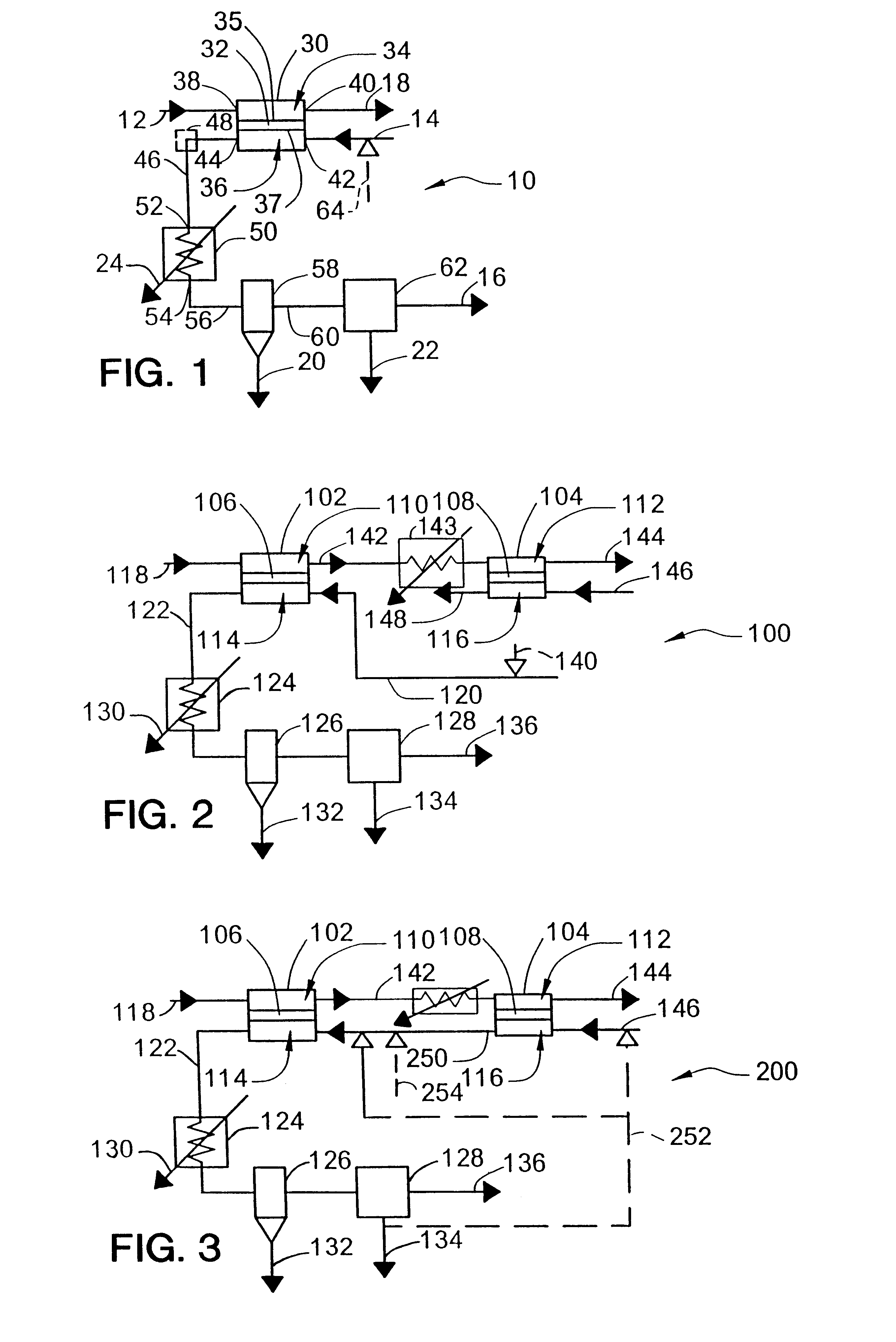
In the system 100 of FIG. 2, each ionic / mixed conducting membrane reactor module may be composed of 1000 tubes, each 10 feet long and 1 inch in diameter. The total surface area of the tubes is about 2,618 ft.sup.2 (calculated as the average of the total area of the cathode side surfaces and the anode side surfaces). The oxygen flux is known to decrease with decreasing oxygen concentration on the cathode side, so there is an estimated oxygen flux of 10 standard cubic feet per hour per square foot (scf / hr / ft.sup.2) for oxygen concentrations greater than 7% (the first reactor 102) and an oxygen flux of 5 scf / hr / ft.sup.2 for oxygen concentrations less than 7% (the second reactor 104). In this case, the two reactors will be the same size and the oxygen concentration will be reduced from 21% to 7% in the first reactor and from 7% to 0% in the second reactor. The total amount of oxygen removed in each module of the first reactor 102 is about 2,150 lb / hr, or 25,800 standard cubic feet per h...

example 2

An alternative for CO.sub.2 production is to use the purge stream from the second ionic / mixed conducting membrane reactor to purge the first reactor in the system 200 of FIG. 3. This process uses the same number of modules as Example 1, consumes the same amount of air as Example 1, and produces the same amount of nitrogen.

However, it produces up to 50% more CO.sub.2. The reason for such a dramatic improvement is that this system takes advantage of the fuel converted on the anode of the second ionic / mixed conducting membrane reactor while the process in FIG. 2 does not. It is expected that additional purification would be necessary with this process compared to the process in Example 1.

example 3

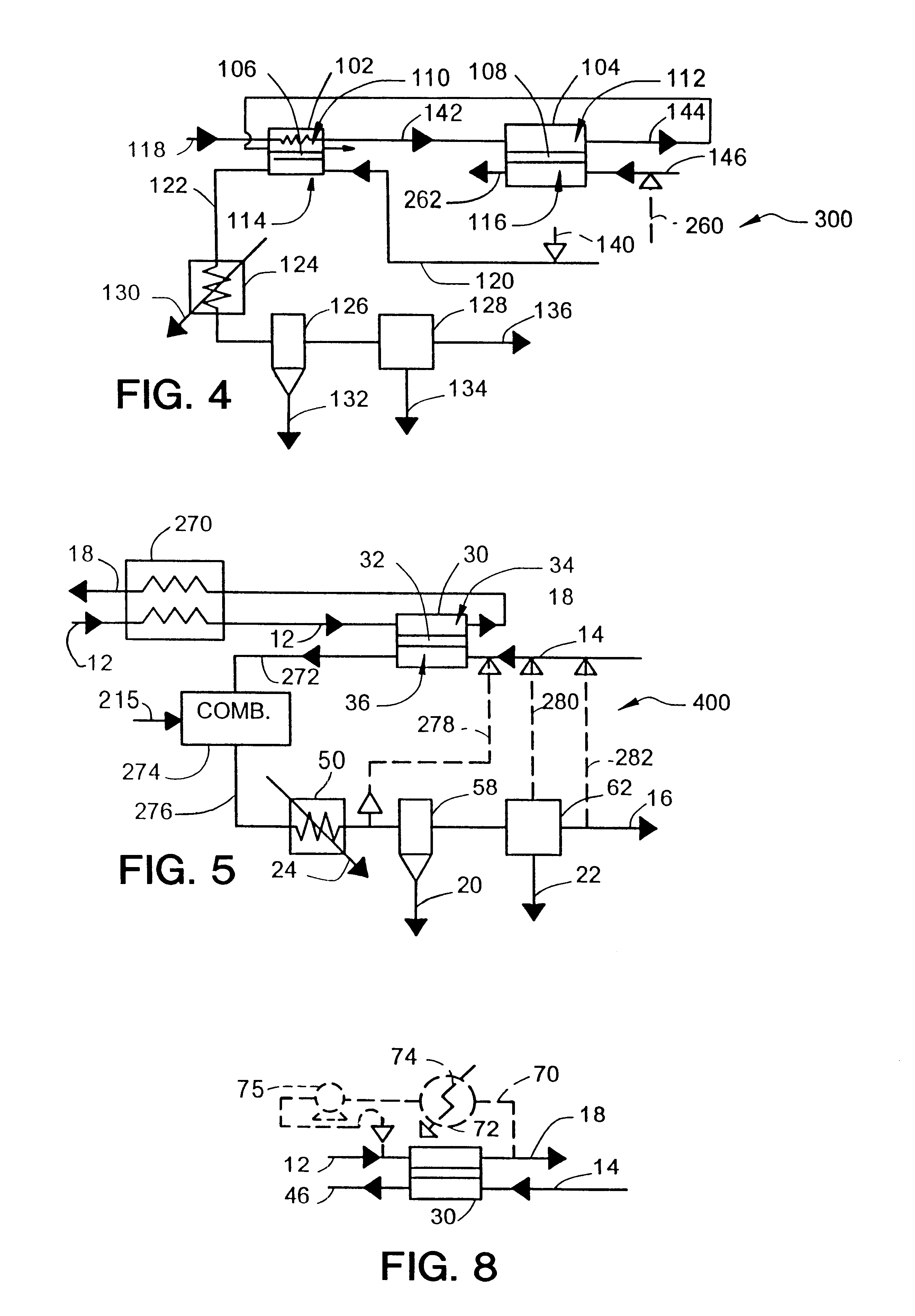
An alternative process involves the use of the second reactor to produce synthesis gas, as in the system 300 of FIG. 4. In this process, the CO.sub.2 reactor 102 will be smaller than the synthesis gas reactor 104 and will serve to preheat the oxygen-depleted gas stream 142 fed to the synthesis gas reactor. In this example, the synthesis gas reactor typically runs at a higher temperature (1,800.degree. F. instead of 1,700.degree. F.). The temperature increase reduces the amount of unconverted methane and complete combustion products. The oxygen flux is also expected to increase at the higher temperature. Some of the extra heat can be recovered by heat exchange or by producing steam. Additional heat exchangers will be needed to preheat the inputs to the reactors because the temperature is higher and because the partial oxidation reaction to produce synthesis gas is much less exothermic than the complete combustion reaction to produce CO.sub.2.

The reactor module size in this example is...


PUM

PropertyMeasurementUnit
Temperatureaaaaaaaaaa
Pressureaaaaaaaaaa
Poweraaaaaaaaaa

Abstract

In a method for the production of carbon dioxide, an oxygen-containing first process gas is flowed along a cathode side of a first oxygen selective ion transport membrane. The membrane is at operating conditions effective to transport a first permeate oxygen portion from the cathode side to an opposite anode side. A carbon-containing second process gas is flowed along the anode side at a flow rate effective to provide a stoichiometric surplus of oxygen on combination with the first permeate oxygen portion. A first mixture of a second process gas and the first permeate oxygen portion is combusted such that substantially all of the second process gas is converted into a second mixture of water and carbon dioxide. The carbon dioxide is separated from such second mixture.

Description

This invention relates to the use of solid electrolyte ionic conductor systems, and in particular to oxygen-selective ion transport membranes (OTM's) in gas separation systems and most particularly to the use of OTM's in gas purification systems.Non-cryogenic bulk oxygen separation systems, for example, organic polymer membrane systems, have been used to separate selected gases from air and other gas mixtures. Air is a mixture of gases which may contain varying amounts of water vapor and, at sea level, has the following approximate composition by volume: oxygen (20.9%), nitrogen (78%), argon (0.94%), with the balance consisting of other trace gases. An entirely different type of membrane, however, can be made from certain inorganic oxides. These solid electrolyte membranes are made from inorganic oxides typified by calcium-or yttrium-stabilized zirconium and analogous oxides having a fluorite or perovskite structure.Although the potential for these oxide ceramic materials as gas sep...

Claims


Application Information

Patent Timeline
IPC IPC(8): B01D53/22B01D53/32F02C6/00B01J19/08C01B21/04C01B32/50C04B35/00C04B35/50
CPCB01D53/22B01D53/32Y02E20/14Y02C10/10Y02C20/40C01B32/50
Inventor PRASAD, RAVIGOTTZMANN, CHRISTIAN FRIEDRICHKESKAR, NITIN RAMESHSCHWARTZ, JOSEPH MICHAEL
Owner PRAXAIR TECH INC
Why Eureka
Try Eureka