
Projection exposure method and apparatus

a technology of projection exposure and projection, applied in the direction of microlithography exposure apparatus, printers, instruments, etc., can solve the problems of poor resolution, limited use of glass materials, and limited use of quartz or fluorite as glass materials

Inactive Publication Date: 2001-10-30
NIKON CORP
View PDF27 Cites 106 Cited by
  • Summary
  • Abstract
  • Description
  • Claims
  • Application Information

AI Technical Summary

Problems solved by technology

If a projection optical system for excimer stepper is composed only of refracting lenses, the glass materials usable therefor are limited to quartz or fluorite.
Then, even if the projection optical system could be produced with high numerical aperture, the depth of focus would be insufficient, which would be a hindrance in practical use.
As a result, the resolution is poor in a portion where the surface unevenness or curvature exceeds the D.O.F. in a shot area (a square of about 20 mm to 30 mm) on the wafer.
The SHRINC method can enjoy the desired effect with a periodic pattern formed on the reticle, but no such effect can be expected for an isolated pattern such as a contact hole.
However, sharpness of resist image obtained after development is inevitably lowered, because the FLEX method requires multiple exposure of contact hole image in a slightly defocused state.
It is, however, found that with a plurality of contact hole patterns closely juxtaposed at a certain distance either one of the above methods causes undesirable film reduction in photoresist between the holes and that they cannot be virtually used for close contact hole patterns.
Further, the FLEX method can increase the depth of focus for isolated contact hole pattern on one hand, while it has such a problem that the exposure dose latitude or margin has to be decreased to maintain the sharpness of synthetic optical image obtained by multiple exposure on the other hand.
The FLEX method also has other problems such as difficult application to exposure apparatus of scanning exposure method or a great drop in processing capability.
However, in case that a plurality of steppers are used in exposure operation in lithography and if the most efficient operational use is considered for each stepper, it is hesitated to assign a specific stepper for exclusive use for exposure of contact hole patterns.

Method used


Image

  • Projection exposure method and apparatus
  • Projection exposure method and apparatus
  • Projection exposure method and apparatus

Examples


embodiments 1-3 to 1-6

solved these problems, which will be described below. In these embodiments, the polarization property of illumination light ILB is changed using the polarization control element 6, as shown in FIGS. 8A to 8C.

FIG. 8A shows an example using a polarizing plate 6A as the polarization control element 6, with which the randomly polarized light from the mercury lamp is converted into linearly polarized light.

FIG. 8B shows an example using a combination of polarizing plate 6A as the polarization control element 6 and a quarter-wave plate 6B. The polarizing plate 6A converts the randomly polarized light into linearly polarized light, and the quarter-wave plate 6B converts the linearly polarized light into right-handed or left-handed circularly polarized light.

FIG. 8C shows an example using only a quarter-wave plate 6B as the polarization control element 6. If the light source emitting linearly polarized light, such as a laser, is used, illumination light ILB reaching the reticle is circularl...

embodiment 1-3

In EMBODIMENT 1-3 the direction of linear polarization can be also changed in such an arrangement that the half-wave plate FA.sub.1 is replaced by an optical rotatory material such as quartz crystal.

Next shown in EMBODIMENT 1-5 and EMBODIMENT 1-6 are constructions of PCM suitable for circularly polarized illumination light ILB. When the incident beam is circularly polarized, the direction of axis of half-wave plate or quarter-wave plate need not be rotated in accordance with polarization property of illumination light, which is convenient.

In EMBODIMENT 1-5 PCM 105 is basically the same as PCM 103 as described above. Then the direction of rotation of circularly polarized light is inverted after passing through the half-wave plate FA.sub.1, while the direction of rotation of circularly polarized light is not changed after passing through the transmissive portion FB.sub.2 for example of quartz plate. In EMBODIMENT 1-3 or EMBODIMENT 1-5, the annular transmissive portion FB.sub.1 may be ...

embodiment 1-9 and embodiment 1-10

are next described.

In EMBODIMENT 1-9, PCM 109 has a triple structure of a central, circular transmissive portion FA.sub.1, an immediately-adjacent, peripheral, annular transmissive portion FB.sub.2 and a further peripheral, annular transmissive portion FB.sub.3. The circular transmissive portion FA.sub.1 and the outermost annular transmissive portion FB.sub.3 are polarizing plates which transmit a beam in the same polarization state, and the intermediate annular transmissive portion FB.sub.2 is a polarizing plate which transmits a beam in a polarization state perpendicular thereto. An emergent beam from PCM 109 is polarized in directions as shown. A beam through the circular transmissive portion FA.sub.1 is in a polarization state different in polarization direction from that through the intermediate annular transmissive portion FB.sub.2, which increases the depth of focus according to the principle as described hereinbefore. Further, a beam through the circular transmissive portion...


PUM


Abstract

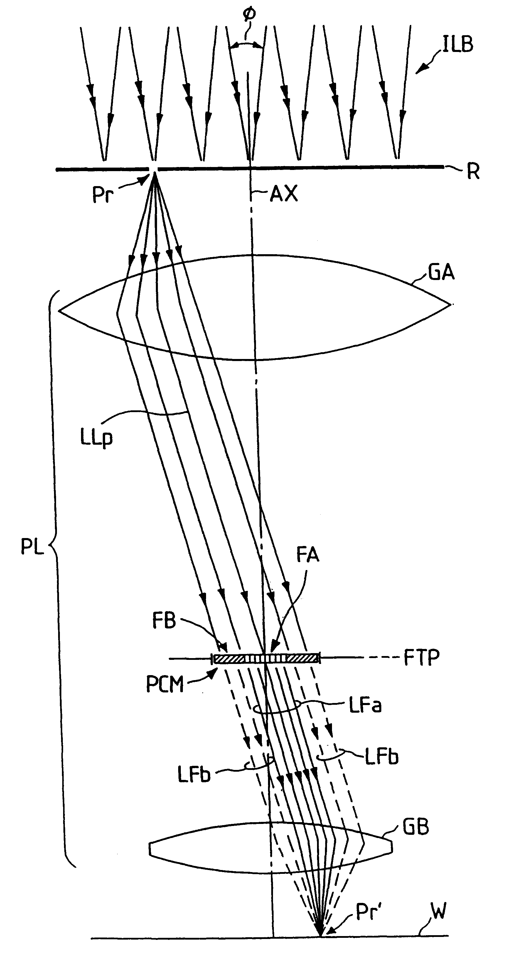
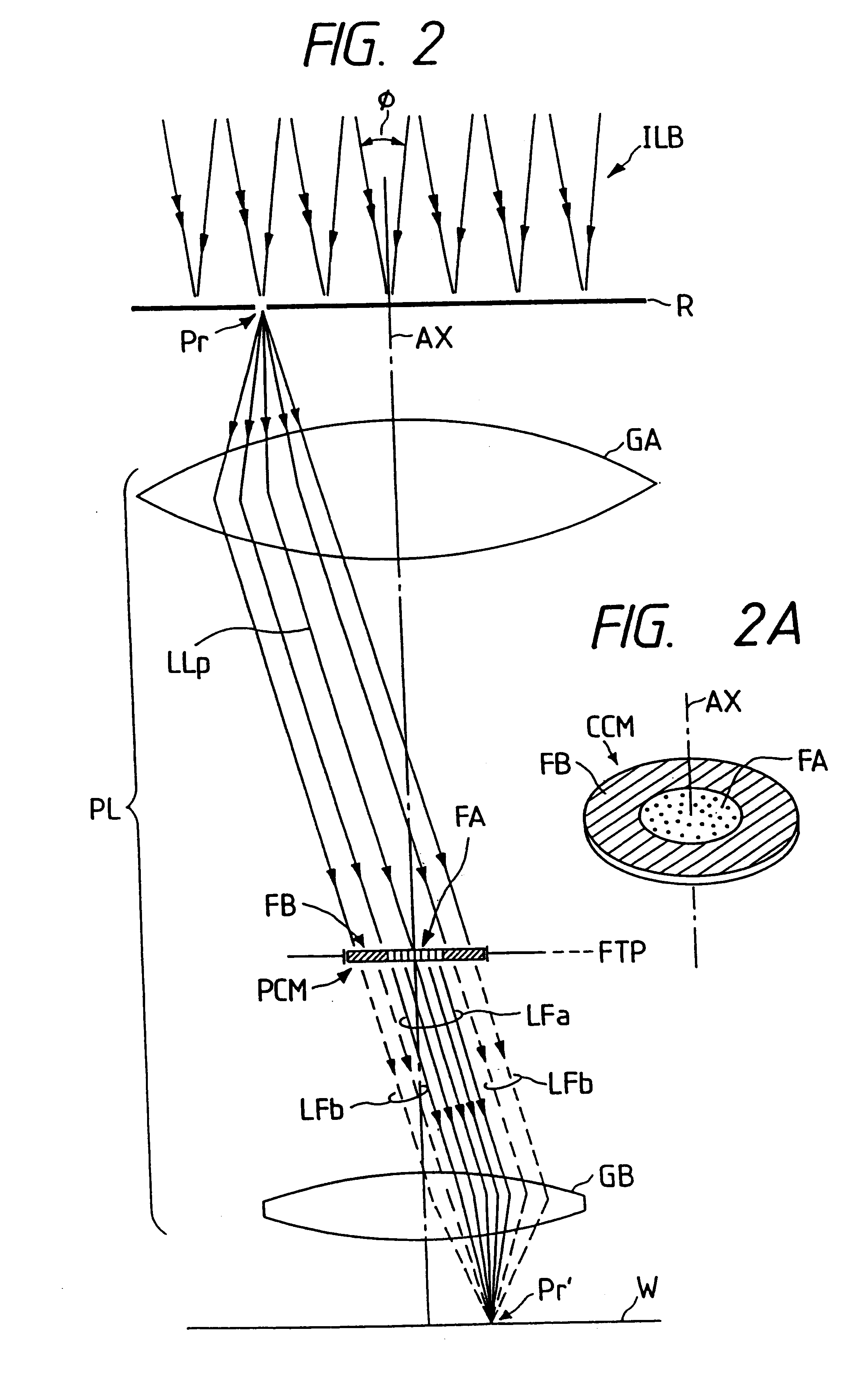
In projection exposure of isolated pattern such as a contact hole, in order to increase the depth of focus a coherence reducing member is disposed on a Fourier transform plane in an image-forming optical path between a mask and a sensitized base, so that coherence is reduced between image-forming beams respectively passing through a plurality of different, concentric regions around the optical axis of the projection optical system on the Fourier transform plane. The coherence reducing member may be a polarization state control member for making a difference in polarization state, a member for making a difference in optical path length, or space filters with different shapes.

Description

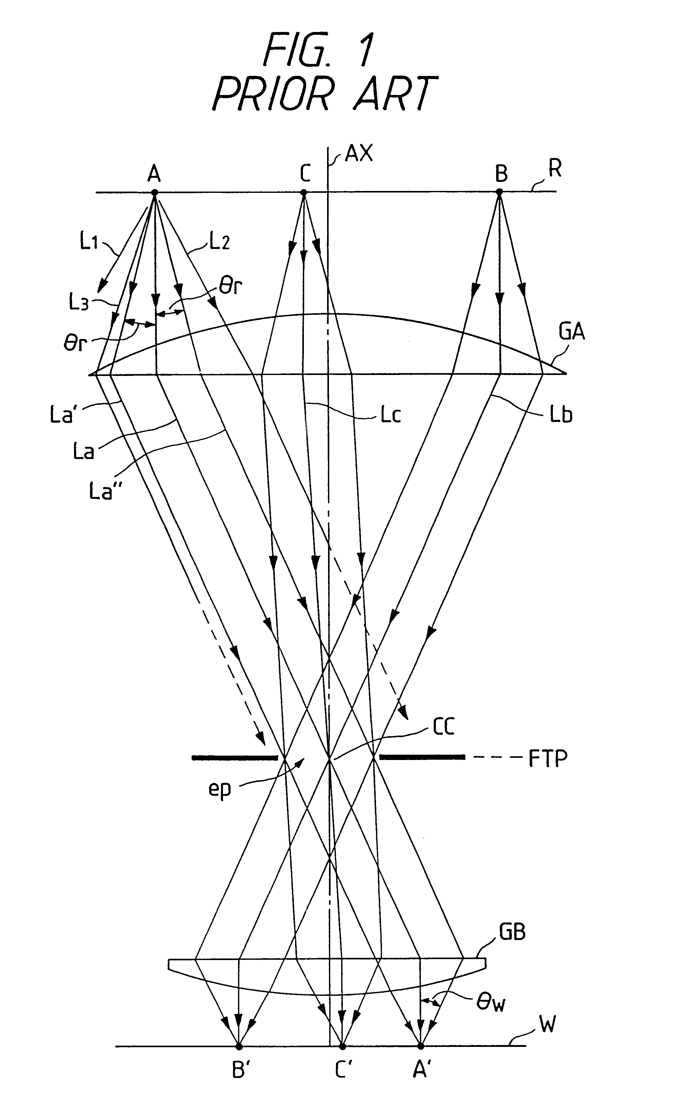
1. Field of the InventionThe present invention relates to projection exposure method and apparatus used in forming fine patterns for semiconductor integrated circuits, liquid crystal displays, or the like.2. Related Background ArtA projection exposure apparatus as called as a stepper is provided with a projection optical system. This projection optical system is incorporated into the exposure apparatus after it is produced in the steps of high-level optical design, strict selection of glass materials, superfine machining of glass materials, and precise assembly and adjustment.Current steppers actually used in fabrication of semiconductors are so arranged that illumination light of i-line (wavelength 365 nm) from a mercury lamp illuminates a photomask as called as a reticle and that a projection optical system focuses light passing through a circuit pattern on the reticle to form an image thereof on a photosensitive substrate such as a wafer. On the other hand, excimer steppers emplo...

Claims


Application Information

Patent Timeline
IPC IPC(8): G03F7/20
CPCG03F7/70258G03F7/70308G03F7/70333G03F7/70566G03F7/70583G03F7/70058
Inventor SHIRAISHI, NAOMASA
Owner NIKON CORP
Learn More