Solid state electrolytes and methods of production thereof

a technology of solid state electrolytes and alkali metal sulfide, which is applied in the direction of electrolytes, electrochemical generators, cell components, etc., can solve the problems of inability to use practicality and inhibit the material of battery electrodes, and achieve stable solid state electrolytes, high voltage stability, and excellent battery cycle performance.

Active Publication Date: 2020-11-05
PRESIDENT & FELLOWS OF HARVARD COLLEGE
View PDF1 Cites 4 Cited by
  • Summary
  • Abstract
  • Description
  • Claims
  • Application Information

AI Technical Summary

Benefits of technology

[0006]We have developed a solid state electrolyte having a core-shell morphology for use in a rechargeable battery. The electrolytes disclosed herein are advantageous as they have high voltage stability and excellent battery cycle performance. The invention also provides a design strategy from a predictive formalism to further stabilize solid state electrolytes by microstructure modifications, and more generally by volume constriction or pressurization that can be realized on both materials and battery cell levels.
[0007]In one aspect, the invention features a solid state electrolyte containing an alkali metal and a sulfide and having a core-shell morphology, wherein the shell increases the stability of the solid state electrolyte during electrical cycling by reducing expansion of the core.
[0009]In a related aspect, the invention features a method of fabricating a solid state electrolyte by mixing together a S source, a P source, a Si source and an alkali metal salt and annealing the mixture to form a sulfide solid state electrolyte having alkali metal atoms and halogen atoms incorporated therein. The annealing occurs, e.g., under conditions to produce a solid state electrolyte with a core-shell morphology, e.g., having increased stability from a reduction in core expansion during electrical cycling.

Problems solved by technology

Despite the promise of sulfide-based SSEs, incompatibility with the lithium chemical potentials of battery electrode materials has inhibited their practical use.

Method used


Image

  • Solid state electrolytes and methods of production thereof
  • Solid state electrolytes and methods of production thereof
  • Solid state electrolytes and methods of production thereof

Examples


example 1

ng the Stability of Core-Shell Electrolyte Powders Using DFT

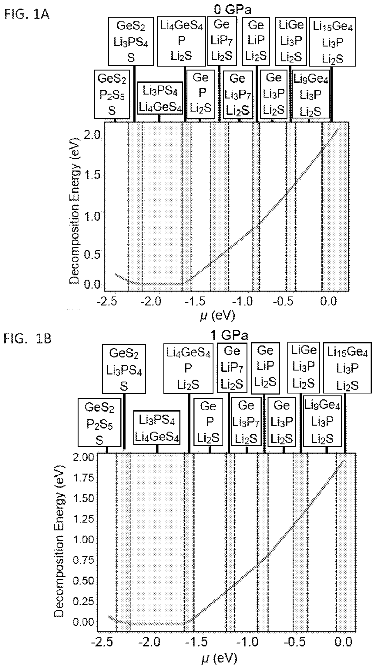
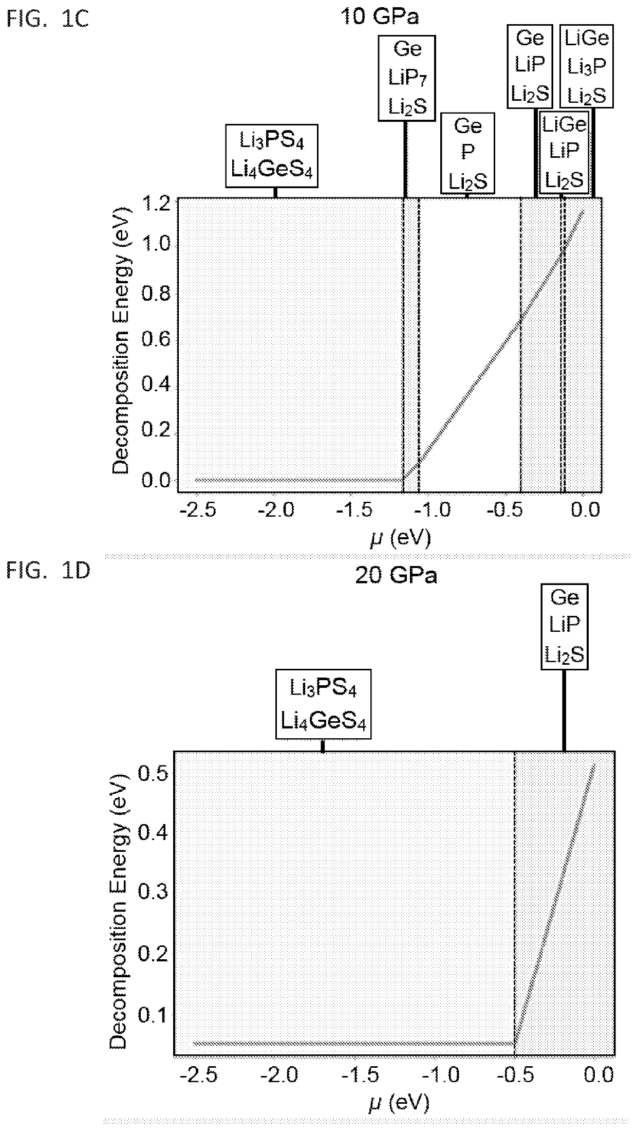
[0090]Our DFT simulation and further analyses based on the formalism described herein shows that LSPS decay remains largely unchanged with doping and initial composition in a zero-pressure environment. This suggests a narrow voltage stability window similar to the related solid state electrolyte, Li-doped germanium-phosphorous-sulfur (LGPS) at zero pressure 19,20 (FIG. 3A). The application of a shell with certain rigidity greatly improves the stability window (FIG. 3B). Additionally, Equation 1 underestimates the reaction strain as the decay converts a single crystal solid electrolyte to a polycrystalline mixture. In the latter case, perfect packing is unlikely. If the decay products have a packing efficiency of η, then the reaction strain would be given by equation 12:

ϵRXN=Vdη-1-VSEVSE(12)

[0091]FIG. 3C illustrates the significant potential impact of such a packing efficiency increases the voltage stability window, suggesti...

example 2

of Chloride Doped Li Ion Sulfide-Based Solid State Electrolytes

[0096]The starting materials used for the synthesis of Li9.54Si1.74P1.44S11.7Cl0.3 solid state electrolyte were Li2S (>99.9% purity, Alfa Aesar), P2S5 (>99% purity, Sigma Aldrich), SiS2 (>99% purity, American Elements) and LiCl (>99% purity, Alfa Aesar). All of the reagents were weighed in the appropriate molar ratio and then placed into a ZrO2 ball-mill jar containing ZrO2 milling balls. All of the procedures were conducted under an argon atmosphere inside a glove box. The mixture was then mechanically milled using a planetary ball milling facility for 40 h. Following the ball milling procedure, the mixture was sealed into glass tubes and then heated at 400° C., 450° C., 460° C., 470° C., 480° C., 490° C., and 500° C., respectively, for 8 h, followed by a slow cooling procedure back to room temperature.

example 3

cterization of Different Sulfide-Based Solid State Electrolytes

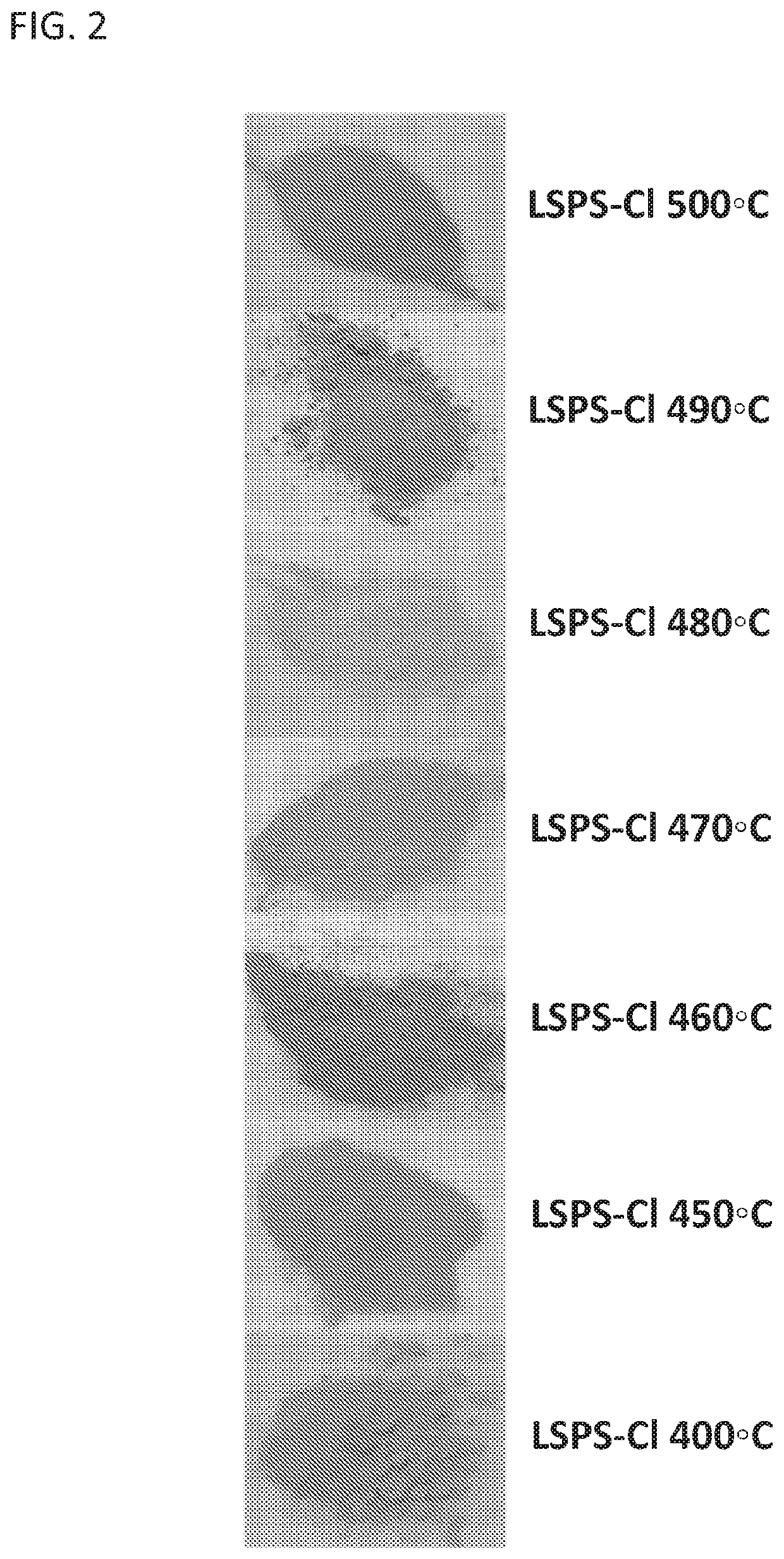
[0097]Li9.54Si1.74P1.44S11.7Cl0.3 powders (LSPS-Cl) were synthesized at 7 different annealing temperatures ranging from 400° C. to 500° C. The colors of the as-synthesized LSPS-Cl powders shown in FIG. 2 change along with the annealing temperature from 400° C. to 500° C. For example, LSPS-Cl annealed at 450° C. shows a red color, while the LSPS-Cl annealed at 400° C. has a white color. Despite the different colors, all of the as-synthesized LSPS-Cl powders annealed at various temperatures were confirmed to belong to the same space group, P42 / nmc(137), by X-ray diffraction (XRD). XRD data were obtained using a Rigaku Miniflex 6G with a Cu target X-ray source (wavelength=1.54056 Å). The various LSPS-Cl powders were placed onto standard XRD sample holders and sealed with Kapton film and vacuum grease under an argon atmosphere in a glove box. Structural parameters were refined in the Topas software using the Rietveld refinem...


PUM

PropertyMeasurementUnit
Young's modulusaaaaaaaaaa
temperatureaaaaaaaaaa

Abstract

The invention provides compositions containing a solid state electrolyte (SSE) containing an alkali metal and a sulfide for use as the electrolyte matrix in a solid state rechargeable battery. The SSE compositions may further contain phosphorous, silicon, or a dopant atom, such as a halogen. These compositions are advantageous as they use Earth-abundant elements, have high voltage stability, excellent battery cycle performance, and are fabricated and used under conditions that do not require excessive external pressures which would otherwise limit their use in a production battery. In particular, the SSEs have a controllable microstructure, e.g., core-shell structure, that enhances their inherent stability while obviating the need for excessively large pressures to control the electrolyte stability. Methods of producing the compositions and rechargeable batteries including the composition are also provided.

Description

FIELD OF THE INVENTION[0001]The invention is directed to the field of alkali metal sulfide solid state electrolytes and solid state batteries.BACKGROUND OF THE INVENTION[0002]The fast development of portable electronic devices and electric vehicles benefits from lithium ion batteries with high power, energy density and safety1-5. These applications demand a solid state electrolyte with good chemical compatibility, high Li ion conductivity and a wide electrochemical stability window. Solid state batteries using solid state electrolytes such as polymers6-8, oxides9-12 or sulfides13-16 hold promise for the next generation lithium ion batteries.[0003]High Li ion conductivity has been achieved in various solid state electrolytes. Solid state electrolytes (SSEs), such as Li10SiP2S12 (LSPS) and its doped derivatives, show promise in terms of ion conductivity for use in all solid state batteries13,16-18. In fact, LSPS may be more conductive than traditional liquid electrolytes. Future batte...

Claims


Application Information

Patent Timeline
Patent Type & Authority Applications(United States)
IPC IPC(8): H01M10/0562H01M10/0525
CPCH01M2300/0094H01M2300/0068H01M10/0525H01M10/0562H01M4/62H01M4/364H01M4/131H01M10/052H01M4/134H01M4/366H01M4/382Y02E60/10
Inventor LI, XINWU, FANFITZHUGH, WILLIAM
Owner PRESIDENT & FELLOWS OF HARVARD COLLEGE
Why Eureka
Try Eureka