
Separator and electrochemical device including the same

a technology of electrochemical devices and separators, which is applied in the direction of cell components, final product manufacturing, sustainable manufacturing/processing, etc., can solve the problems of insufficient discharge capacity, difficult manufacture, and low capacity of lithium ion polymer batteries, and achieve excellent adhesion with electrodes and improve porous structur

Active Publication Date: 2019-05-02
LG ENERGY SOLUTION LTD
View PDF2 Cites 14 Cited by
  • Summary
  • Abstract
  • Description
  • Claims
  • Application Information

AI Technical Summary

Benefits of technology

The present invention is about a coating process for a thin film battery. The process involves coating a porous layer onto an electrode using a binder polymer and an adhesive porous layer. This adhesive porous layer is formed through a dry phase separation process, which improves its porous structure and reduces the problem of resistance. The result is a coating that ensures uniformity and excellent adhesion with the electrode.

Problems solved by technology

However, such lithium ion batteries have a problem of ignition and explosion caused by the use of an organic electrolyte and a disadvantage of a difficulty in manufacture.
However, such lithium ion polymer batteries still have a relatively low capacity as compared to lithium ion batteries and particularly show an insufficient discharge capacity at low temperature.
With regard to safety characteristics of electrochemical devices, there is great concern about explosion when an electrochemical device is overheated to cause thermal runaway or perforation of a separator.
Particularly, a polyolefin-based porous substrate used conventionally as a separator for an electrochemical device shows a severe heat shrinking behavior at a temperature of 100° C. or higher due to its material property and a characteristic during its manufacturing process, including orientation, thereby causing a short-circuit between a cathode and an anode.

Method used


Image

  • Separator and electrochemical device including the same
  • Separator and electrochemical device including the same
  • Separator and electrochemical device including the same

Examples


example 2

[0118]A separator was manufactured in the same manner as Example 1, except that acetone as a solvent and isopropanol as a non-solvent were mixed at a weight ratio of 80:20 and polyvinylidene fluoride-co-hexafluoroproyplene (PVdF-HFP) as an adhesive resin was added thereto in an amount of 2 parts by weight based on 100 parts by weight of the combined weight of acetone and isopropanol and dissolved therein at 50° C. for about 12 hours when preparing a coating composition for an adhesive porous coating layer.

[0119]The resultant separator had an asymmetric structure on both surfaces in the order of adhesive porous layer / porous polymer substrate / porous coating layer / adhesive porous layer.

[0120]In addition, in the separator, the porous coating layer and the adhesive porous layer had a thickness of 2 μm and 1 μm, respectively.

example 3

[0121]Polyvinylidene fluoride-co-hexafluoroproyplene (PVdF)-HFP as a binder was added to acetone and dissolved therein at 50° C. for about 12 hours or more to prepare a binder polymer solution. To the resultant binder polymer solution, alumina (Al2O3) particles having an average particle diameter of 500 nm as non-boehmite particles and boehmite (γ-ALO(OH)) particles having an average particle diameter of 250 nm were added, and then dispersed therein to obtain a slurry for a porous coating layer.

[0122]The obtained slurry was coated onto both surface of a polyethylene porous membrane (porosity 40%) having a thickness of 12 μm through a slot coating process and the coating thickness was controlled to about 1.25 μm to obtain a separator provided with a porous coating layer on both surfaces thereof.

[0123]In the porous coating layer, the binder polymer was 5 wt % based on the total weight of the porous coating layer and the weight ratio of the boehmite particles: binder polymer was 1:1.2....

example 4

[0128]A separator was manufactured in the same manner as Example 1, except that acetone as a solvent and methanol as a non-solvent were mixed at a weight ratio of 80:20 and polyvinylidene fluoride-co-hexafluoroproyplene (PVdF-HFP) as an adhesive resin was added thereto in an amount of 2 parts by weight based on 100 parts by weight of the combined weight of acetone and isopropanol and dissolved therein at 50° C. for about 12 hours when preparing a coating composition for an adhesive porous coating layer.

[0129]The resultant separator had an asymmetric structure on both surfaces in the order of adhesive porous layer / porous polymer substrate / porous coating layer / adhesive porous layer.

[0130]In addition, in the separator, the porous coating layer and the adhesive porous layer had a thickness of 2 μm and 1 μm, respectively.


PUM

PropertyMeasurementUnit
porosityaaaaaaaaaa
thicknessaaaaaaaaaa
dielectric constantaaaaaaaaaa

Abstract

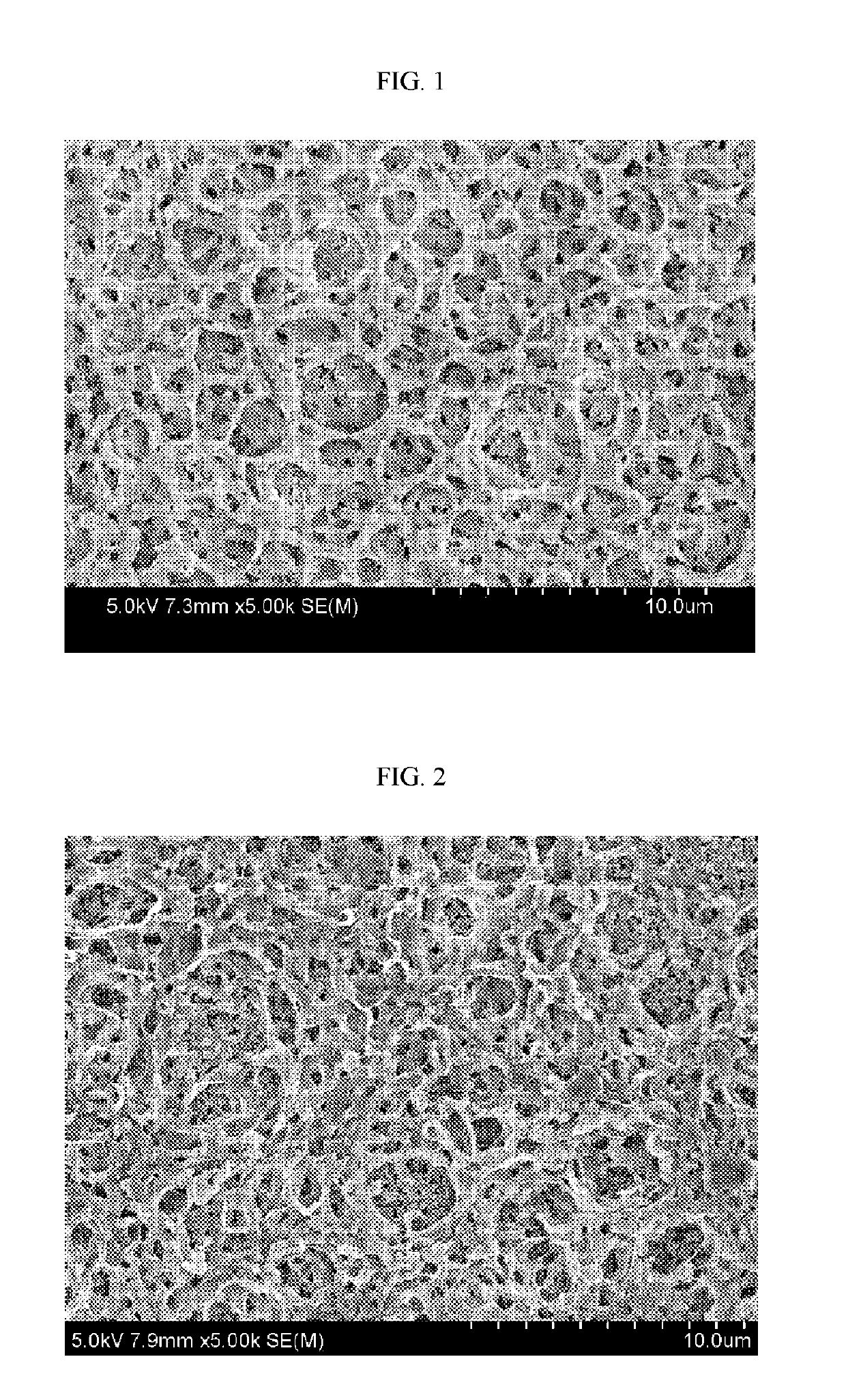
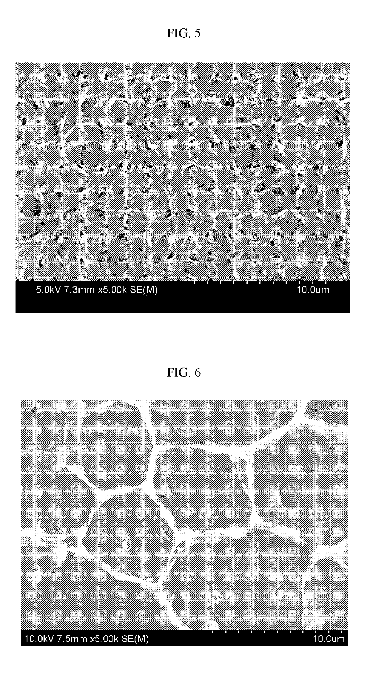
Disclosed are a separator and an electrochemical device including the same. The separator includes: a porous polymer substrate having a plurality of pores; a separator base including a porous coating layer formed on at least one surface of the porous polymer substrate, and including a plurality of inorganic particles and a binder polymer disposed partially or totally on the surface of the inorganic particles to connect and fix the inorganic particles with each other; and an adhesive porous layer formed on at least one surface of the separator base and including an adhesive resin which shows adhesive property through heating at a temperature lower than the melting point of the porous polymer substrate, wherein the adhesive porous layer is provided with a porous structure formed by phase separation caused by the evaporation rate of a solvent and that of a non-solvent, when applying and drying a coating composition including the adhesive resin, the solvent and the non-solvent on at least one surface of the separator base.

Description

TECHNICAL FIELD[0001]The present disclosure relates to a separator and an electrochemical device including the same. Particularly, the present disclosure relates to a separator having improved adhesion with an electrode and an excellent effect of reducing resistance, and an electrochemical device including the same.[0002]The present application claims priority to Korean Patent Application No. 10-2016-0101471 filed on Aug. 9, 2016 in the Republic of Korea, the disclosures of which are incorporated herein by reference.BACKGROUND ART[0003]Recently, energy storage technology has been given an increasing attention. Efforts into research and development for electrochemical devices have been actualized more and more, as the application of energy storage technology has been extended to energy for cellular phones, camcorders and notebook PC and even to energy for electric vehicles. In this context, electrochemical devices have been most spotlighted. Among such electrochemical devices, develo...

Claims


Application Information

Patent Timeline
Patent Type & Authority Applications(United States)
IPC IPC(8): H01M2/16H01M2/14H01M10/0525H01M50/403H01M50/417H01M50/449H01M50/489H01M50/491
CPCH01M2/1686H01M2/166H01M2/1653H01M2/145H01M10/0525H01M10/052H01M10/4235H01M2300/0068Y02E60/10H01M50/403H01M50/461H01M50/446H01M50/449H01M50/417H01M50/489H01M50/491H01M50/451H01M50/414H01M50/4295H01M50/431H01M50/443C08K3/12Y02P70/50
Inventor YOON, SU-JINKWON, HYE-JINKIM, MIN-JIKIM, CHAN-JONGNAM, KWAN-WOO
Owner LG ENERGY SOLUTION LTD
Learn More