
Analytical x-ray tube with high thermal performance

a technology of x-ray tubes and thermal performance, applied in the field of x-ray tubes, can solve the problems of limited maximum brightness, thermal limitation of tubes, and relatively inefficient electron impact excitation of x-rays, and achieve the effects of improving thermal properties, dissipating heat from the anode, and high brightness

Active Publication Date: 2019-02-21
BRUKER AXS
View PDF0 Cites 15 Cited by
  • Summary
  • Abstract
  • Description
  • Claims
  • Application Information

AI Technical Summary

Benefits of technology

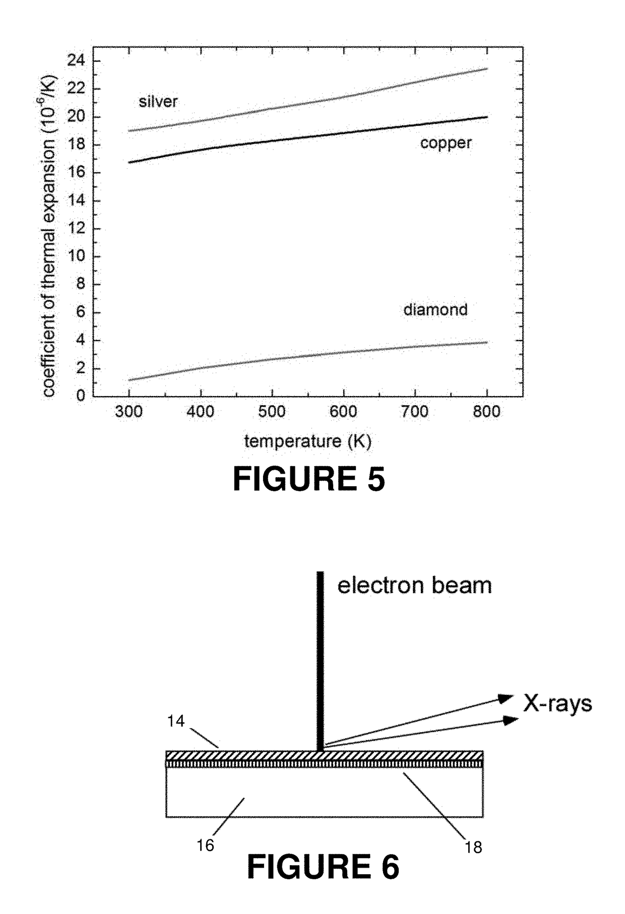
The present invention provides an X-ray tube with improved thermal properties that allows for the generation of brighter X-rays. The X-ray tube includes a target anode with a target material that emits characteristic X-rays in response to excitation by an electron beam. The target anode is located on a diamond substrate that dissipates heat from the anode. An intermediate layer between the diamond substrate and the target material can provide a more stable bond with the diamond material to resist against shear stresses. The target material can be a low thermal conductivity material, such as chromium, molybdenum, rhodium, or tungsten, and a heat dissipation layer with significantly higher thermal conductivity than the target material can be included between the target layer and the diamond substrate to enhance heat dissipation.

Problems solved by technology

The process of electron impact excitation of X-rays is relatively inefficient.
This means that tubes are thermally limited, that is, that the maximum brightness is limited by thermal decomposition of the anode via melting or evaporation.
Although the use of such a substrate material has allowed for enhanced heat dissipation, and therefore higher brightness X-ray beams, there are still limitations to the overall performance of such tubes.

Method used


Image

  • Analytical x-ray tube with high thermal performance
  • Analytical x-ray tube with high thermal performance
  • Analytical x-ray tube with high thermal performance

Examples


Embodiment Construction

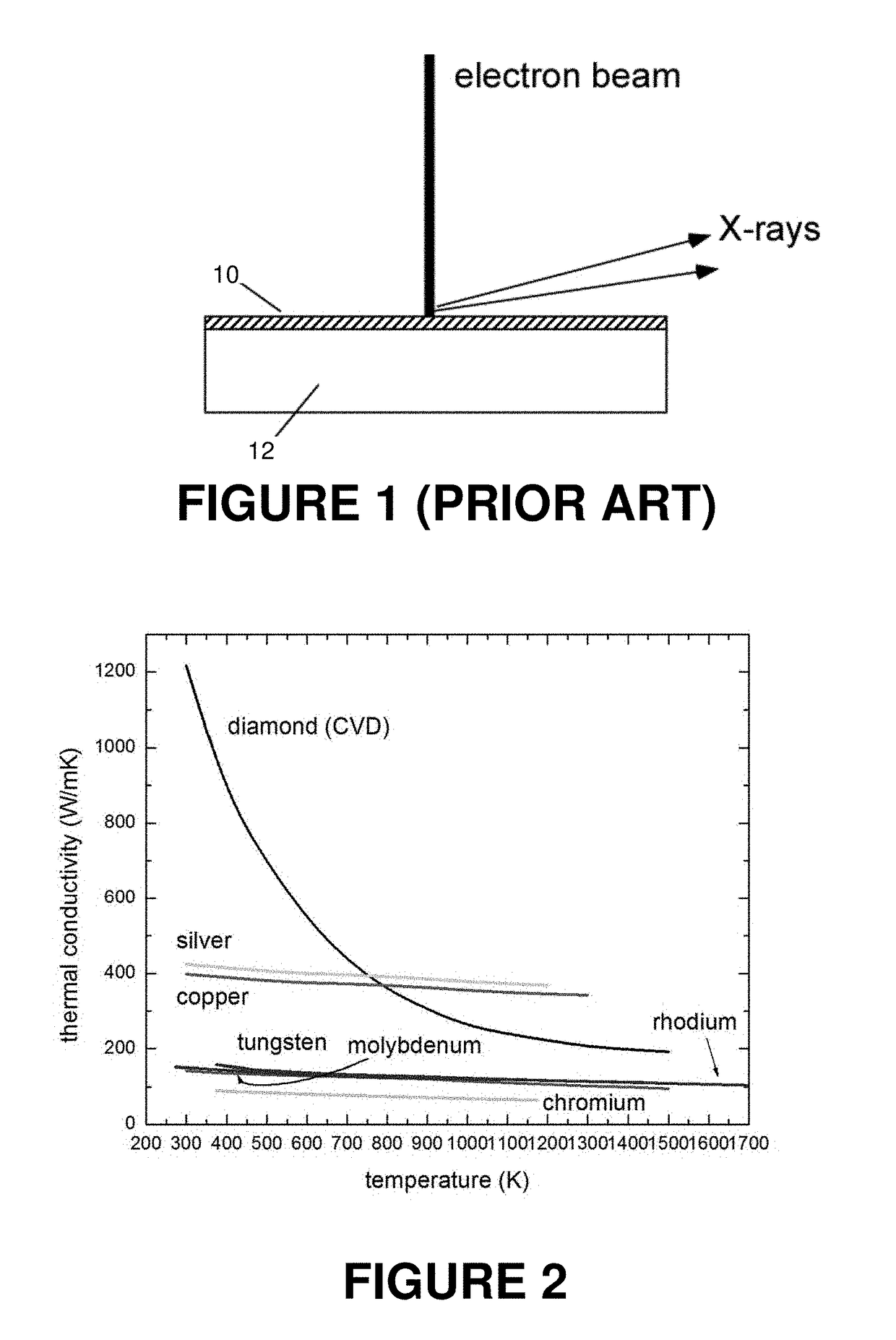
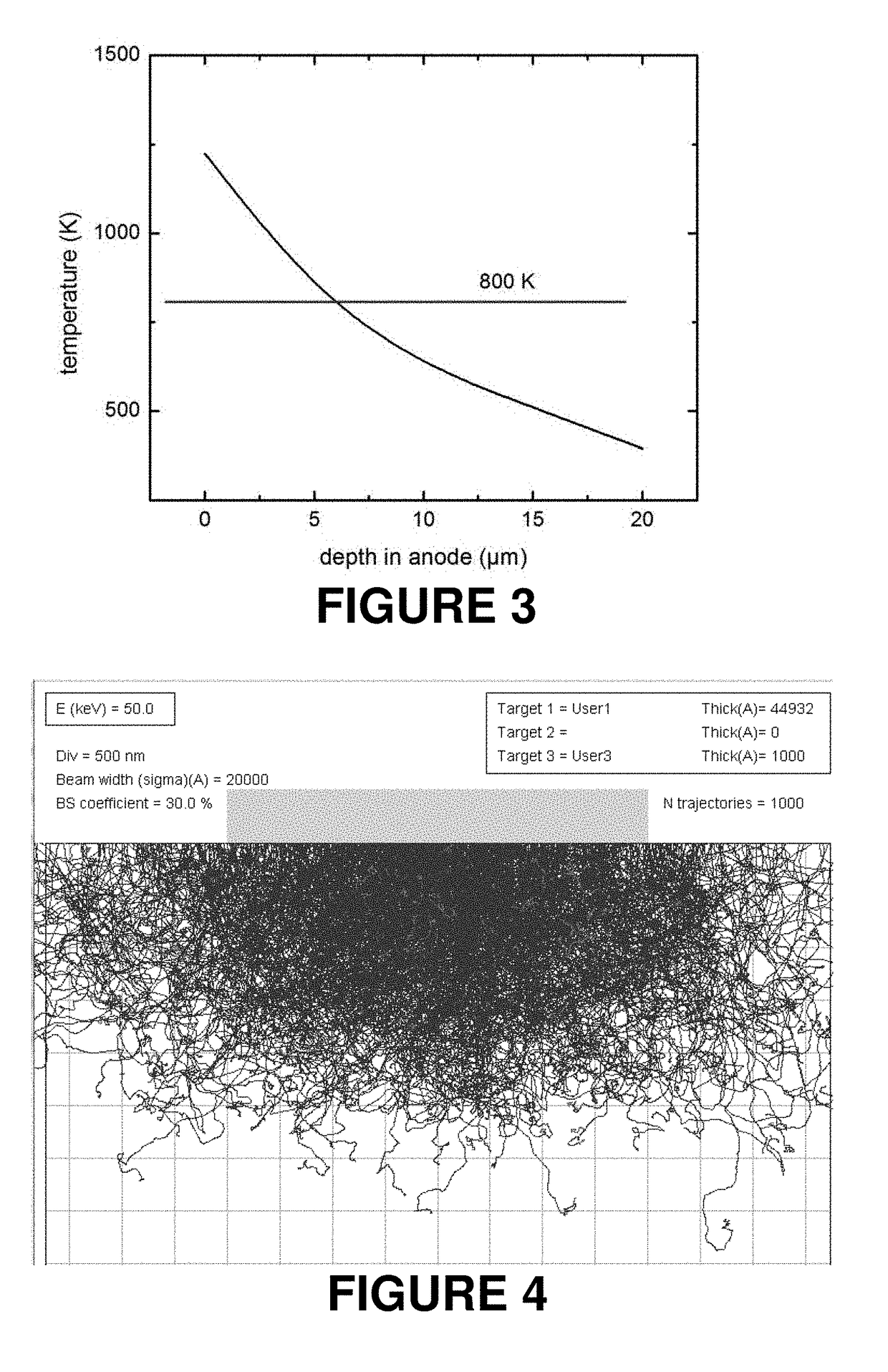
[0020]Although diamond substrates have been used in the past as a means for dissipating heat from a target material located thereupon, a number of practical difficulties still exist in X-ray tubes that use such an arrangement. FIG. 2 shows a plot of the thermal conductivity of diamond and metals commonly used in analytical X-ray tubes relative to temperature. As shown, diamond has a thermal conductivity that is significantly higher than copper or silver at room temperature, typically by a factor of three or four for synthetic (chemical vapor deposited) diamond. This makes diamond an attractive choice for a substrate in certain applications, but the thermal conductivity advantage that it provides is only present at relatively lower temperatures. At higher temperatures, above about 800 K, the thermal conductivity of both copper and silver exceeds that of diamond.

[0021]In practice, analytical X-ray tubes are frequently operated at temperatures approaching their melting point so as to m...


PUM

PropertyMeasurementUnit
operating temperatureaaaaaaaaaa
depthaaaaaaaaaa

Abstract

An analytical X-ray tube with an anode target material that emits characteristic X-rays in response to excitation by an electron beam may include any of several advantageous features. The target material is deposited on a diamond substrate layer, and a metal carbide intermediate layer may be provided between the target material and substrate that provides enhanced bonding therebetween. An interface layer may also be used that provides an acoustic impedance matching between the target material and the substrate. For a low thermal conductivity target material, a heat dissipation layer of a higher thermal conductivity material may also be included between the target material and substrate to enhance thermal transfer. The target material may have a thickness that corresponds to a maximum penetration depth of the electrons of the electron beam, and the structure may be such that a predetermined temperature range is maintained at the substrate interface.

Description

BACKGROUND OF THE INVENTIONField of the Invention[0001]This invention relates generally to the field of X-ray tubes and, more specifically, to the high power density generation of X-rays at a desired wavelength for use in analytical instruments.Description of the Related Art[0002]In X-ray tubes, a high energy electron beam (typically 10-100 keV) impinges on a target material to excite X-ray emission. In the case of X-ray tubes used for analytical applications, such as X-ray diffraction, the tubes are optimized to produce characteristic radiation at a particular wavelength. The most common X-ray tubes used for such applications incorporate target anodes comprised of chromium, cobalt, copper, molybdenum, silver rhodium or tungsten. The choice of the anode material is based upon the desired X-ray wavelength for the analytical application in question.[0003]The process of electron impact excitation of X-rays is relatively inefficient. Typically, only about 1% of the energy of the inciden...

Claims


Application Information

Patent Timeline
Patent Type & Authority Applications(United States)
IPC IPC(8): H01J35/08H01J35/10G03F7/36H01J35/12G03F7/16
CPCH01J35/08H01J35/108G03F7/36H01J35/12G03F7/16H01J35/105H01J2235/186H01J2235/081H01J2235/084H01J2235/087H01J2235/1291H01J2235/183H01J2235/1204H01J2235/1295H01J35/116H01J35/186
Inventor DURST, ROGER D.MICHAELSEN, CARSTENRADCLIFFE, PAULSCHMIDT-MAY, JENSS
Owner BRUKER AXS
Learn More