Unfortunately, as the distance between the source of a digital message and its destination increases, and the travel over multiple networks increases, accurate transmission or reception of transmitted data at the reception point, becomes increasingly more problematic.
This problem is exacerbated when different protocols are employed in a single message or when errant problems in cables and along communications channels which may affect on signal protocol, but not another.
Inaccurate or unusable data can result from numerous sources along a transmission pathway where electronic
noise is communicated into a signal path, or where connections have corroded, or become loose, or a plethora of other reasons.
A flawed transmission component, or reception component, or a damaged line, or low or
high voltage, or spurious magnetic fields, or many other problems can cause improper signal communication along the pathway which can easily result in damaged or unusable data at a reception component.
As noted, in addition to the potential for flaws in the operation of transmission and reception components and bugs in operating
software, another source of flawed digital communications results from the electrical
distortion of the electronic signals transmitted which must travel through long conductors or
signal pathways.
The longer the pathway the signal must follow on the communications channel, the more potential exists for electronic
noise to be added to the electronic signal transmitted.
Thus, as a transmitted signal using one or more protocols propagates through a
transmission medium or pathway, the longer it is between the transmission and reception point, the more potential exists for
noise being imparted to the signal.
While inside a small facility, precautions can be taken to protect the electronic communications and
data exchange between the transmission and reception components, the problems caused by electronic noise significantly increase when data is transferred between devices over a network, or plurality of engaged networks.
In many cases, the resulting
distortion of the received signal from a
transmission point, can become so severe that information sent to a receiving point on the communications channel is lost or severely impaired.
However, noise and momentary electrical disturbances such as
voltage variances or frequency variances, EMF energy, and other types of electrical interference, have a
high potential to cause non-
continuous signal anomalies which occur in the signal transmitted across the channel from the source.
Such electrical anomalies can easily cause changes in the transmitted data as it passes through a communications channel which render portions unemployable during reassembly with the appropriate protocol, or yield errors in the communication on reassembly.
This of course can cause significant changes in the discerned data on the receiving end of the channel using the appropriate protocol for the transmission, thus communicating unuseable or intelligible data to the reception point.
The potential for such
data transmission errors also can occur where the transmission hardware using electronic components for generating the electronic signal according to the protocol used, or with the reception hardware itself.
These malfunctions can be caused by malfunctioning components yielding errors in the signal varying from the
transmission protocol employed.
Or, the receiving electronic device can also error in discerning the incoming signal due to malfunctioning components.
For the
technician attempting to ascertain the reason that the reception point suffers from lost or unusable data or impaired data communications on the communications channel, a problem arises.
Reloading of
software or
firmware can also be prone with its own set of potential problems.
However, with the current state of the art, the
technician has no reliable means to determine whether the communications problems in an electronic signal carry a
data transmission are caused by noise and
voltage variances on the communications channel or the transmission and reception equipment or
software.
As such, repairs may be initiated which are expensive and
time consuming and which do not remedy the problem.
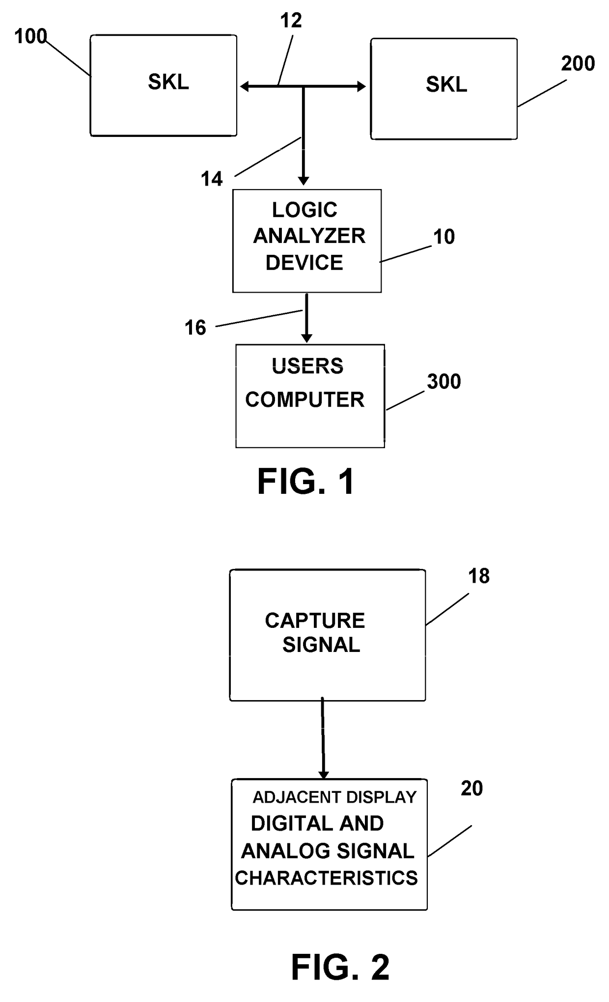
Signal communication errors which occur between two machines, for example ECUs, SKL's, and other telecommunication devices, when data which is sent or received is not within the specification of the communication protocol, result in a failure to successfully communicate.
If the
voltage, or
signal frequency timing of the signal being transmitted is out of a specified range, the receiving
machine will not be able to successfully identify the content of the signals, and communication between the two machines cannot be achieved.
As noted previously, errors in electronic signal communications over a pathway, including voltage and
signal timing and current frequency and other issues, can frequently result in this key and other signal data improperly reaching the end
machine which upon employing the correct protocol and the key in decoding and deciphering the communication to yield the correct data.
However, in order to ascertain wherein signal anomalies exist, or whether it is a transmission or receiving component mal functioning, electronic signal
troubleshooting and analyzing is required employing the key.
As such, when analyzing and monitoring communications between two machines employing encrypted data, users are typically unable to access the content of the data for the purpose of analyzing such signals without the proper key which the
technician may not have or be security-cleared to employ.
Conventional EKMS analytic methods therefor typically employ
active monitoring and decoding processes which often require
time consuming testing procedures.
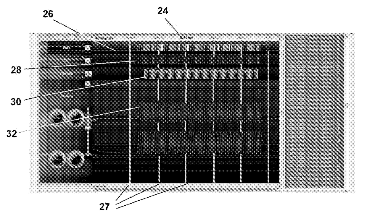
However, such voltage and timing variances may not cause any problems with digital communications which are highly error resistant, and as a consequence observation of an
oscilloscope screen yields little discernible information without concurrently viewing or monitoring of the received discernable data since the errors may be fixed by
retransmission of the packets if errors of such are realized by the modems or communicating devices using the appropriate protocols.
As such, and as noted, conventional analyzing and testing procedures often result in the technician being unable to locate the source or reason for communication errors, and a mis-communication between the machines continues because of the lack of depictions relating to the multiple aspects of electronic signals.
Various limitations of the related art will become apparent to those skilled in the art upon a reading and understanding of the specification below and the accompanying drawings.
