
Implant superstructure

Inactive Publication Date: 2017-08-31
REALITY DENTAL LAB
View PDF10 Cites 0 Cited by
  • Summary
  • Abstract
  • Description
  • Claims
  • Application Information

AI Technical Summary

Benefits of technology

The present invention relates to a new structure for a dental implant that has excellent rigidity even at smaller diameters and heights. The framework is made of a cobalt-chromium alloy, which is stronger than traditional materials like gold alloy, platinum alloy, pure titanium, or titanium alloy. This helps to secure thin artificial teeth for incisors or short-height artificial teeth for molars. The coupling member of the superstructure has lower hardness than the fixture, preventing deformation and reducing the need for replacement. The plurality of lateral holes allows for reliable soldering and maintains the strength of the implant. The framework and coupling member are joined together more firmly using a solder introduced through the voids between the cylindrical members. This helps to ensure the proper joining of the components and reliable soldering throughout the clearances between them. Overall, this new structure improves the stability and reliability of dental implants.

Problems solved by technology

However, a cobalt-chromium-alloy framework has a problem with the accuracy of the joint part due to an oxide film formed on the surface during firing of porcelain etc.
Another problem is the difficulty of joining together the cobalt-chromium-alloy framework and the gold-alloy coupling member.
If one attempts to join the two together by cast-joining, as the melting point of the cobalt-chromium alloy is close to the melting point of the gold alloy, the gold-alloy coupling member melts when the cobalt-chromium alloy is melted, which makes cast-joining itself difficult.
Joining the cobalt-chromium alloy and the gold-alloy coupling member by laser welding may result in lower accuracy of joint as the cobalt-chromium alloy is oxidized (corroded) during laser welding.
Moreover, air bubbles are generated at the joint part during laser welding which may cause the holes in the artificial tooth because air is released from the air bubbles while firing process of the powder raw material applied on to the framework to form the artificial tooth.

Method used


Image

  • Implant superstructure
  • Implant superstructure
  • Implant superstructure

Examples


example 1

[0080]A cast body made of a cobalt-chromium alloy and measuring 2 mm in diameter and 20 mm in length was prepared as a first material to be soldered. The cobalt-chromium alloy used was Wirobond280 mentioned above.

[0081]A cast body made of a gold alloy and measuring 2 mm in diameter and 20 mm in length was prepared as a second material to be soldered. The gold alloy used was GoldAdapt mentioned above.

[0082]Next, the first and second materials to be soldered were each cut into 10 cm long pieces with a cutting disc (silicon-carbide, medium-fine “Ultra-thin Multi-Purpose Abrasive Discs” made by Keystone Industries, N.J. USA). Two pieces of the respective materials were butted together with a 30 μm clearance left therebetween and fixed at two points by spot welding with a laser welding machine (Mini-LASER XXS made by OROTIG S.r.l., Garda, Italy).

[0083]Next, the first and second materials to be soldered were subjected to soldering operation by a furnace soldering method, and were then tak...


PUM


Abstract

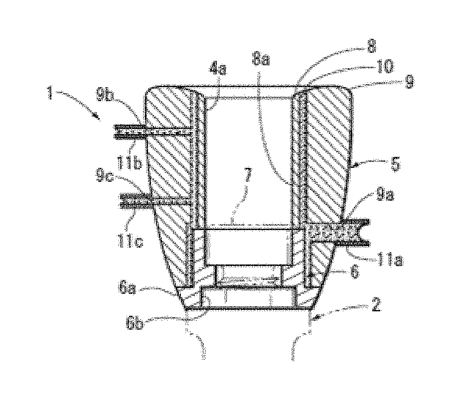
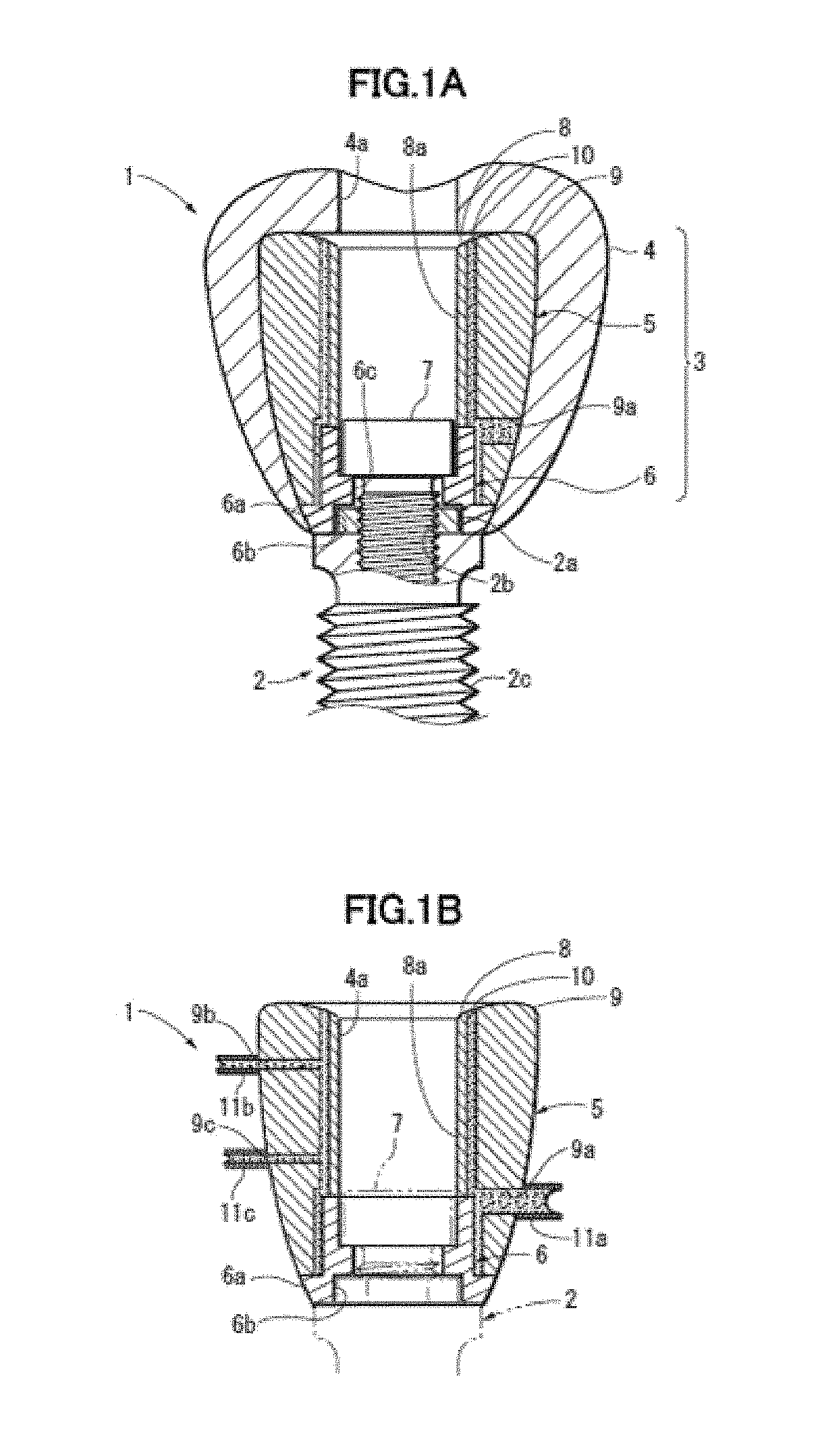
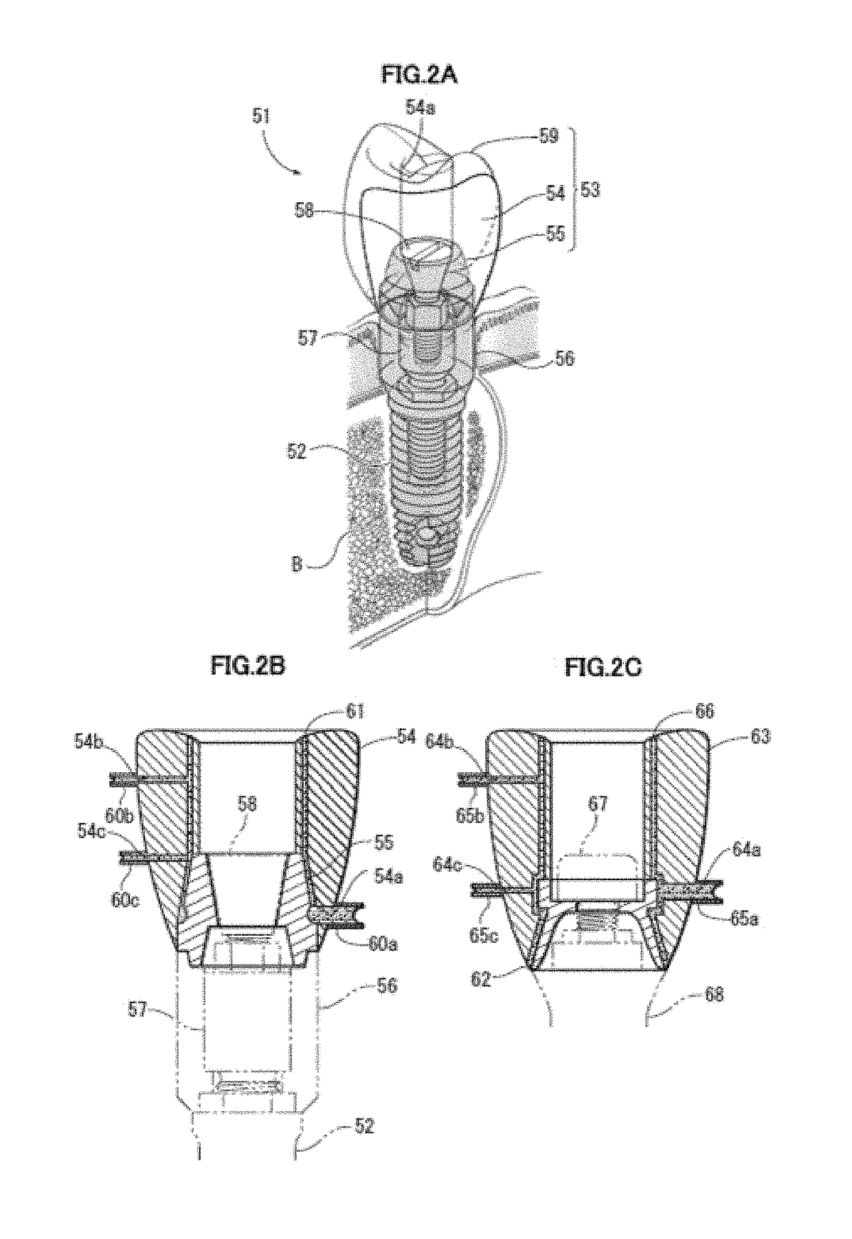
Provided is a superstructure (3) coupled to a fixture (2) that is made of pure titanium or a titanium alloy and planted in a jawbone, the superstructure (3) including: a framework (5) made of a cobalt-chromium alloy; an artificial tooth (4) bonded to the outer surface of the framework (5); and a coupling member (6) made of a gold alloy and joined to a lower part of the inside of the framework (5) to couple the framework (5) to the fixture (2), wherein the framework (5) and the coupling member (6) are integrated by being soldered together with a solder (10) composed of a gold alloy containing gold and silver.

Description

TECHNICAL FIELD[0001]The present invention relates to a superstructure used for implants.BACKGROUND ART[0002]An implant includes a pure-titanium or titanium-alloy fixture planted in a jawbone and a superstructure coupled to the fixture. The superstructure includes a framework, an artificial tooth bonded to the framework, and a coupling member joined to a lower part of the inside of the framework to couple the framework to the fixture.[0003]Conventionally, the framework is made of a gold alloy, a platinum alloy, pure titanium, a titanium alloy, zirconia, or the like in view of biocompatibility, workability, etc. The coupling member is made of an alloy of a noble metal such as gold or platinum, or a framework member is directly processed to serve as the coupling member, especially a gold alloy is preferred in view of corrosion resistance, hardness, and workability. The artificial tooth is made of porcelain, a hard resin, or the like, of which porcelain is preferred in view of wear res...

Claims


Application Information

Patent Timeline
IPC IPC(8): A61C13/09A61C13/10A61C8/00A61C13/01A61C13/20
CPCA61C13/09A61C13/01A61C13/102A61C8/0012A61C13/20A61C8/00A61C8/0048A61C13/0835
Inventor UZAWA, SHINOBUYOSHINARI, MASAO
Owner REALITY DENTAL LAB
Learn More